Installation Cerabar M, Deltabar M, Deltapilot M / 4...20 mA HART
18 Endress+Hauser
3.4 Installing Deltabar M
3.4.1 Installation position
!
Note!
• Due to the orientation of the Deltabar M, there may be a shift in the measured value, i.e. when
the container is empty, the measured value does not display zero. You may correct this zero point
shift by a position adjustment in one of the following ways:
– via the operation keys on the electronics module ( ä 40, "Function of the operating
elements")
– via the operating menu ( ä 56, "Position zero adjustment")
• General recommendations for routing the impulse piping can be found in DIN 19210 "Methods
for measurement of fluid flow; differential piping for flow measurement devices" or the
corresponding national or international standards.
• Using a three-valve or five-valve manifold allows for easy commissioning, installation and
maintenance without interrupting the process.
• When routing the impulse piping outdoors, ensure that sufficient anti-freeze protection is used,
e.g. by using pipe heat tracing.
• Install the impulse piping with a monotonic gradient of at least 10%.
• Endress+Hauser offers a mounting bracket for installing on pipes or walls ( ä 23, "Wall and
pipe-mounting (option)").
Installation position for flow measurement
!
Note!
For more information about differential pressure flow measurement refer to following documents:
• Differential pressure flow measurements with orifices: Technical Information TI00422P
• Differential pressure flow measurement with Pitot tubes: Technical Information TI00425P
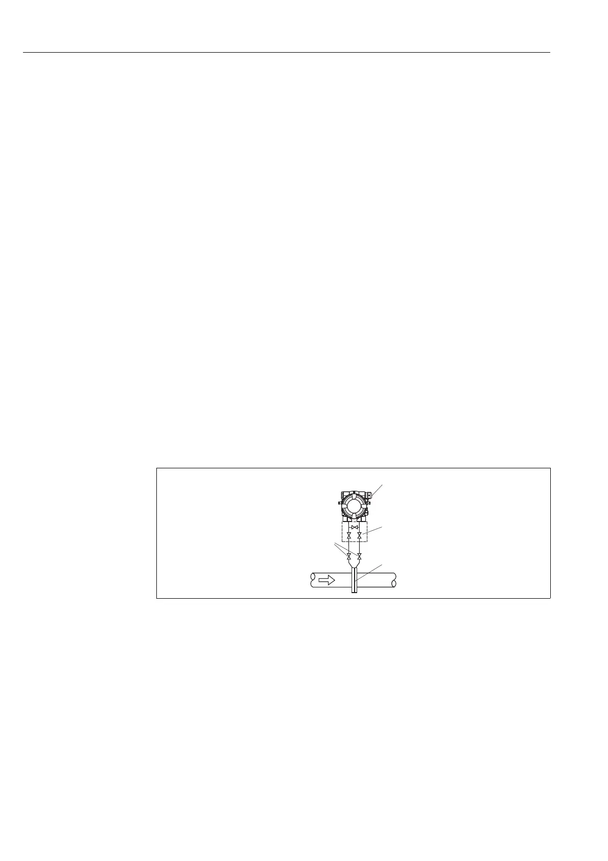
Flow measurement in gases
P01-PMD55xxx-11-xx-xx-xx-000
Measuring layout for flow measurement in gases
1Deltabar M
2 Three-valve manifold
3 Shut-off valves
4 Orifice plate or pitot tube
• Mount the Deltabar M above the measuring point so that the condensate which may be present,
can run off into the process piping.

 Loading...


