Cerabar M, Deltabar M, Deltapilot M / 4...20 mA HART Wiring
Endress+Hauser 31
4 Wiring
4.1 Connecting the device
!
Note!
• When using the measuring device in hazardous areas, installation must comply with the
corresponding national standards and regulations and the Safety Instructions or Installation or
Control Drawings.
• A suitable circuit breaker has to be provided for the device in accordance with IEC/EN 61010.
• Devices with integrated overvoltage protection must be earthed.
• Protective circuits against reverse polarity, HF influences and overvoltage peaks are integrated.
The procedure
1. Check if the supply voltage matches the specified supply voltage on the nameplate.
2. Switch off the supply voltage before connecting the device.
3. Remove housing cover.
4. Guide cable through the gland. Preferably use twisted, screened two-wire cable.
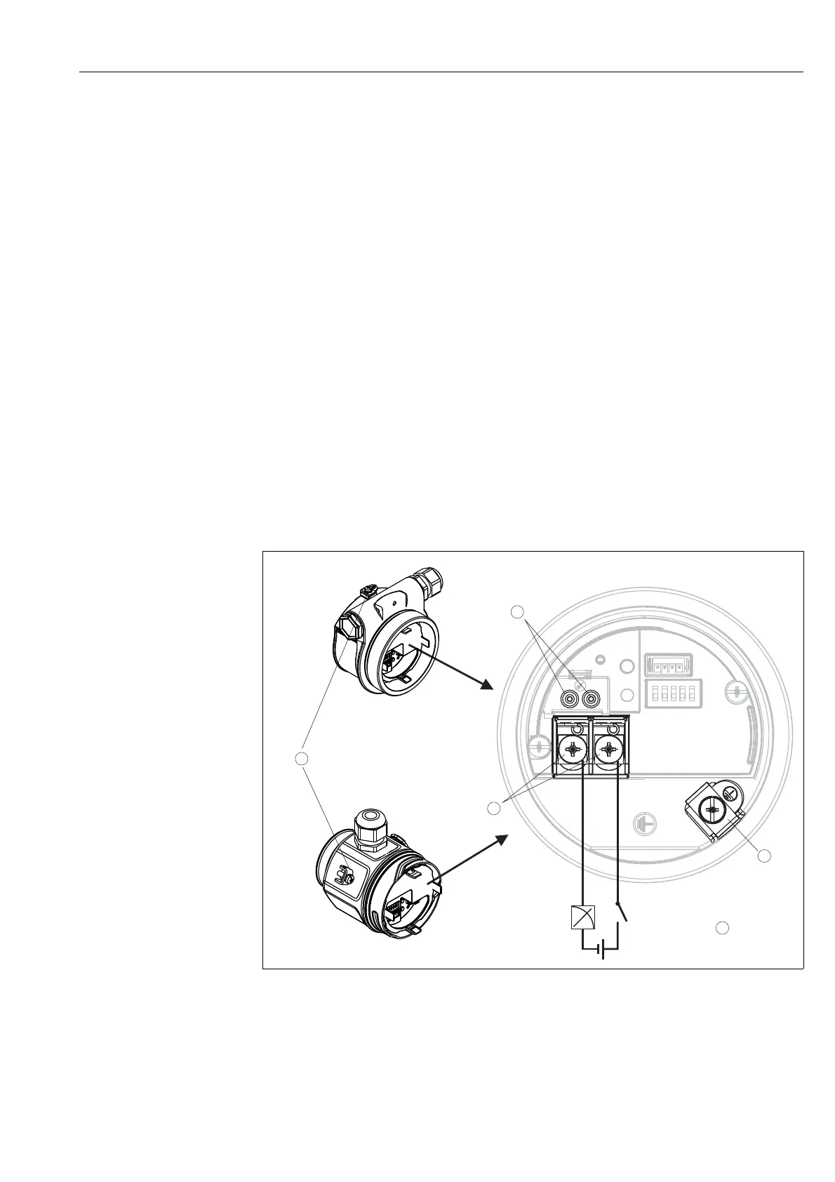
5. Connect device in accordance with the following diagram.
6. Screw down housing cover.
7. Switch on supply voltage.
P01-PMD55xxx-04-xx-xx-xx-010
Electrical connection 4...20 mA HART
1 Terminals for supply voltage and signal
2 Test terminals
3Grounding terminal
4 Supply voltage: 11,5 ... 45 VDC (versions with plug connectors: 35 V DC)
5 External ground terminal

 Loading...


