18
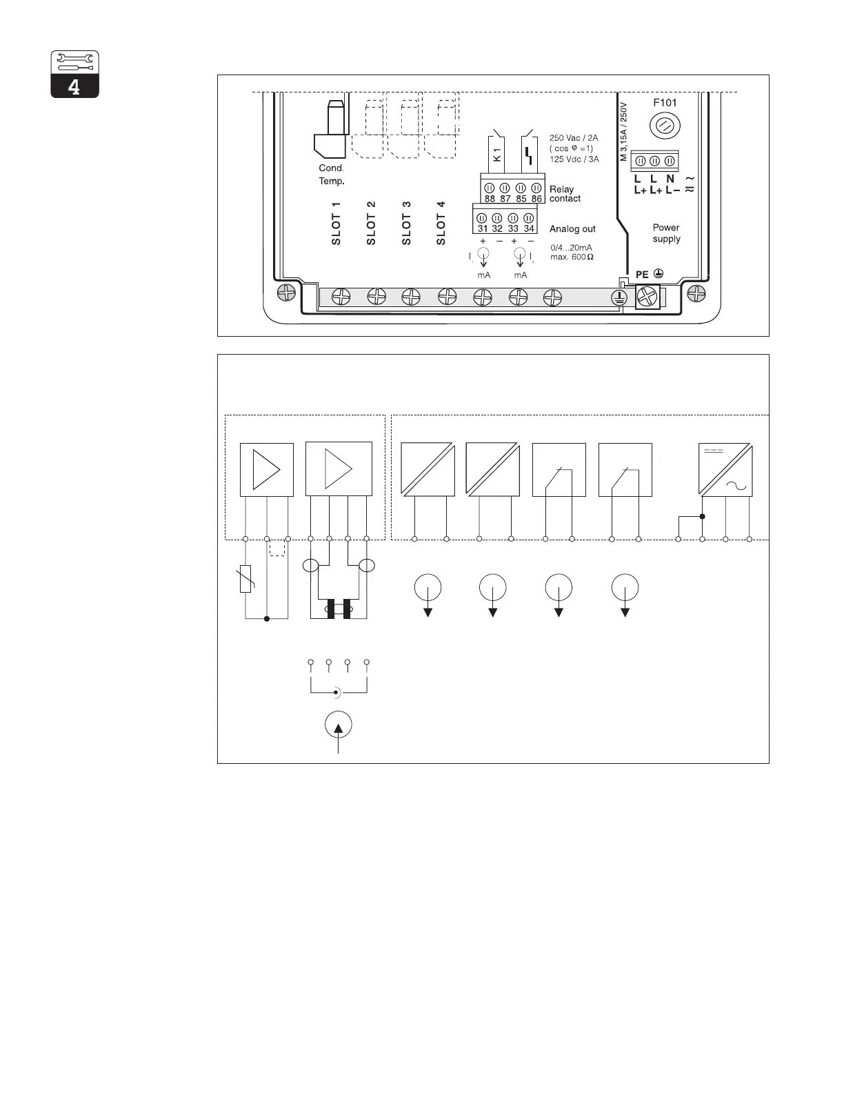
4.4.1 Connection of Mycom CLM 152 in non-Ex (non-hazardous) Areas
Figure 4.6
Connection compartment
of Mycom CLM 152
(basic configuration)
Conductivity input module FCL1
(slot 1)
Motherboard (basic assembly)
Temperature Conductivity Conductivity Temperature Failure Contact 1 Pwr Supply
31 32 33 34 85 86 87 88
AC:
DC:
L
L+
L
L+
PE
Pt100
Figure 4.7
Connection diagram
for Mycom CLM 152
(basic configuration)
FCL1 module (slot 1, basic configuration): Terminal blocks (basic configuration):
11 Pt 100 connection, sensor cable L/L+ Power supply voltage AC phase or DC +
12 Pt 100 connection, sensor cable L/L+ Power supply voltage AC phase or DC +
13 Cable compensation connection N/L Power supply voltage AC neutral or DC
PE Power supply protective ground
For toroidal measuring cell
14 Inner conductor of transm. coil 31 Current output (cond. signal) plus
15 Transmission coil shield 32 Current output (cond. signal) minus
16 Receiving coil shield 33 Current output (temp. signal) plus
17 Inner conductor of receiving coil 34 Current output (temp. signal) minus
For contacting measuring cell 85 Failure contact
14 Inner electrode 86 Failure contact
17 Outer electrode 87 Contact 1
88 Contact 1
11 12 13
N
L
Transmit
Receive
Toroidal
++
Contacting
14 15 16
17
14 15 16 17
n.c.
n.c.
JJ
Cd.
Cd.
mA mA