19
Note!
The contact position in case of power failure or fault can be set for Contact 1
and Failure contact via the system configuration.
All the switching contacts are interference-suppressed with varistors. External
loads that are connected may require additional interference-suppression
measures.
Expansion Module FCL1
For a second conductivity input.
11 Pt 100 connection, sensor cable (gn)
12 Pt 100 connection, sensor cable (wt)
13 Cable compensation connection (ye)
14 Inner conductor of transm. coil
15 Transmission coil shield
16 Receiving coil shield
17 Inner conductor of receiving coil
Measuring channel assignments:
Cond. 1 / temperature 1 slot 2
Cond. 2 / temperature 2 slot 1
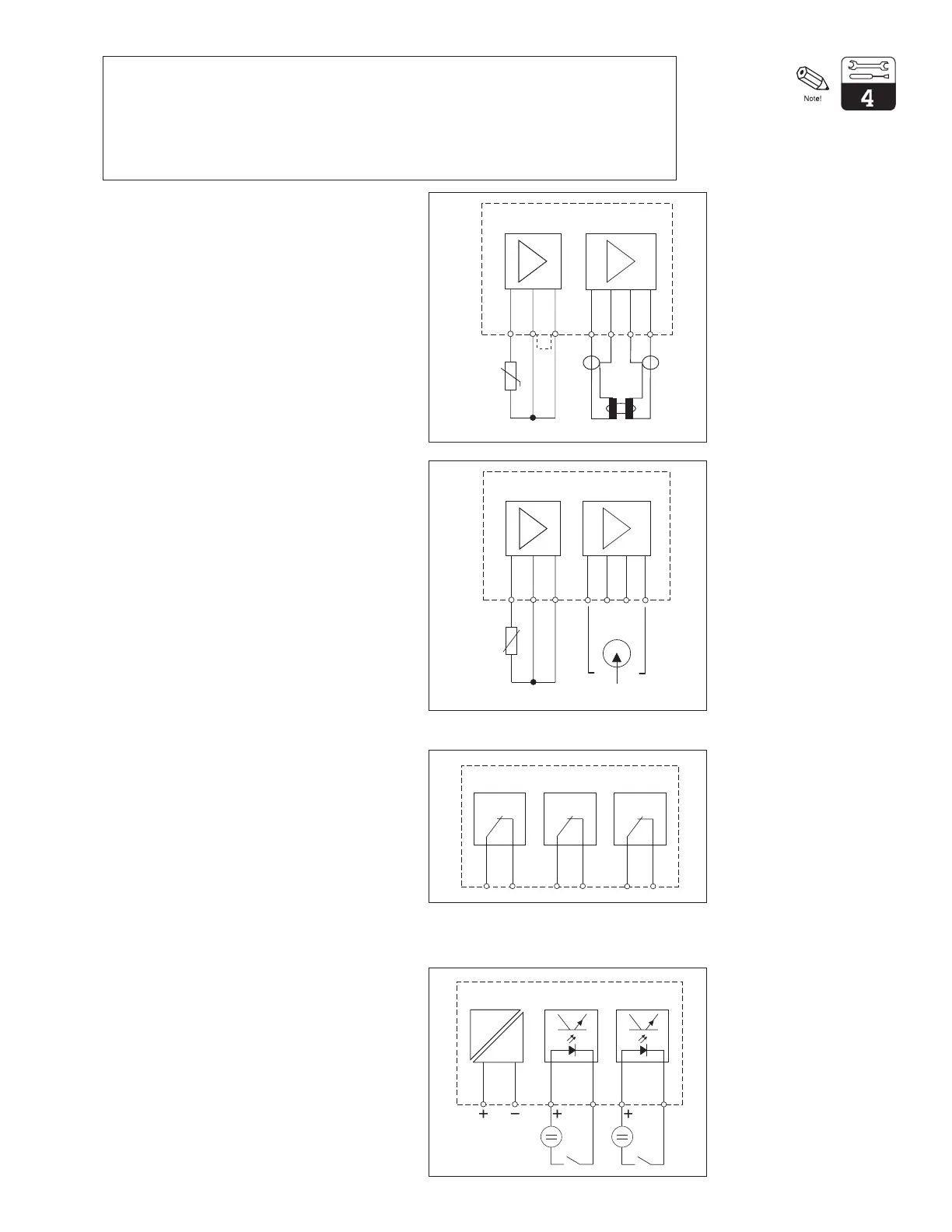
With three (3) relays for limit contacter or
Chemoclean
89 Contact 2
90 Contact 2
91 Contact 3
92 Contact 3
93 Contact 4
94 Contact 4
89 90 91 92 93 94
Contact 2 Contact 3 Contact 4
Expansion Module FCXI:
With two (2) binary input contacts for hold and
remote measuring range switching and an
auxiliary voltage
21 Current input plus
22 Current input minus
81 Binary input 1
82 Binary input 1
83 Binary input 2
84 Binary input 2
Figure 4.8
Connection of module
FCL1 with toroidal
sensor
Figure 4.9
Connection of module
FCL1 with contacting
sensor
Figure 4.10
Connection of module
FCYK, non-Ex
Expansion Module FCYK:
1312
11
Pt 100
14
15
16 17
1312
11
Pt 100
14 15
16
17
11 Pt 100 connection, sensor cable (gn)
1)
12 Pt 100 connection, sensor cable (wt)
1)
13 Cable compensation connection (ye)
1)
1)
with CYK 71 cable
For 2-electrode measuring cell:
14 Inner electrode (inner conductor)
17 Outer electrode (outer conductor)
21 22 81 82 83 84
Current input Binary inputs
mA
Figure 4.11
Connection of module
FCXI