WirelessHART Fieldgate SWG70 Electrical Installation
Endress + Hauser 25
4. Connect the Ethernet cable to the terminal block labeled "Ethernet" according to the
following table.
5. Screw the housing cover on the housing.
6. Tighten the cable gland with appropriate torque. See Chapter 5.5 "Cable glands and
housing cover" on page 27.
7. Switch on the power supply.
5.3.2 Connecting the "EtherNet/IP" version to Ethernet
The Ethernet cable with a D-coded M12 connector is connected to the M12 socket of the
Fieldgate housing.
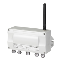
Fig. 5-4: Fieldgate with M12 socket in the middle
1. Switch off the power supply.
2. Plug the D-coded M12 connector into the Ethernet socket of the Fieldgate. See
Figure 5-4 on page 25.
3. Tighten the coupling nuts on the M12 connector. The Fieldgate is connected to the
Ethernet network.
4. Switch on the power supply.
Computer Fieldgate
Pin Numbering Connector Crossover cable Normal cable
Pin 1 TX+ RX+
Pin 2 TX– RX–
Pin 3 RX+ TX+
Pin 4 T2 T2
Pin 5 T2 T2
Pin 6 RX– TX–
Pin 7 T1 T1
Pin 8 T1 T1
1 Ethernet terminal block wired internally to M12
socket
2 M12 socket, D-coded for connection to an
Ethernet or Ethernet/IP network
12345 6 78
KL7 KL8 KL9 KL10
A
B
SHD
RS485
T1
T2
ON
OFF
SHD
A
B
SHD
RS485
E
T1
T2 RX– RX+ TX–
TX+
SHD
ETHERNET
KL11 KL12 KL13
 Loading...
