22
Enertech Global IOM, VS/VT Models, Rev A
Section 5: Unit Piping Installation
Interior Piping
All interior piping must be sized for proper ow rates
and pressure loss. Insulation should be used on all
inside piping when minimum loop temperatures
are expected to be less than 50°F. Use the table
below for insulation sizes with different pipe sizes.
All pipe insulation should be a closed cell and
have a minimum wall thickness of 3/8”. All piping
insulation should be glued and sealed to prevent
condensation and dripping. Interior piping may
consist of the following materials: HDPE, copper,
brass, or rubber hose (hose kit only). PVC is not
allowed on pressurized systems.
Table 3: Pipe Insulation
Piping Material Insulation Description
1” IPS Hose 1-3/8” ID - 3/8” Wall
1” IPS PE 1-1/4” ID - 3/8” Wall
1-1/4” IPS PE 1-5/8” ID - 3/8” Wall
2” IPS PD 2-1/8” ID - 3/8” Wall
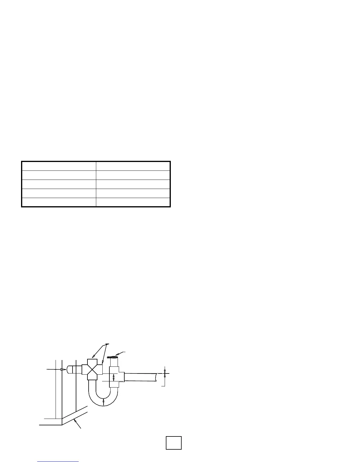
Condensation Drain Connection
Connect the EZ-Trap to the 3/4” equipment
condensate drain connection as shown in Figure 1.
The condensate line must be trapped a minimum of
1.0” as shown in the diagram. The condensate line
should be pitched away from the unit a minimum
of 1/4” per foot. The condensate line from the unit
drain connection to the P-trap should be sloped
downward. For more information on installing EZ-
Trap, see installation sheet that comes with the EZ-
Trap Kit. Always install the air vent after the trap.
Figure 1: Typical Condensation Drain Connection
Cleaning Holes (Capped)
1/4" per foot
Vent
Front of Unit
Unit Condensate
Drain Outlet
1.0”
Note: Connect the drain through the trap to the
condensation drain system in conformance to local
plumbing codes.
Part Number Description
ACDT1A - EZ-Trap ¾” Kit
ACDT2A - EZ-Trap 1” Kit (customer must provide a 1”
S x 3/4” Mips adapter)
Typical Pressurized Flow Center Installation
The ow centers are insulated and contain all
ushing and circulation connections for residential
and light commercial earth loops that require a
ow rate of no more than 20 gpm. 1-1/4” fusion x
1” double o-ring ttings (AGA6PES) are furnished
with the double O-ring ow centers for HDPE loop
connections. Various ttings are available for the
double O-ring ow centers for different connections.
A typical installation will require the use of a hose
kit. Matching hose kits come with double O-ring
adapters to transition to 1” hose connection.
Note: Threaded ow centers all have 1” FPT
connections. Matching hose kits come with the
AGBA55 adapter needed to transition from 1” FPT to
1” hose.
Typical Non-Pressurized Flow Center Installation
Standing column ow centers are designed to
operate with no static pressure on the earth loop.
The design is such that the column of water in the
ow center is enough pressure to prime the pumps
for proper system operation and pump reliability.
The ow center does have a cap/seal, so it is still a
closed system, where the uid will not evaporate. If
the earth loop header is external, the loop system
will still need to be ushed with a purge cart. The
non-pressurized ow center needs to be isolated
from the ush cart during ushing because the ow
center is not designed to handle pressure. Since this
is a non-pressurized system, the interior piping can
incorporate all the above-mentioned pipe material
options (see interior piping), including PVC. The ow
center can be mounted to the wall with the included
bracket or mounted on the oor as long as it is
properly supported.