37
IOM, VS/VT Models, Rev A Enertech Global
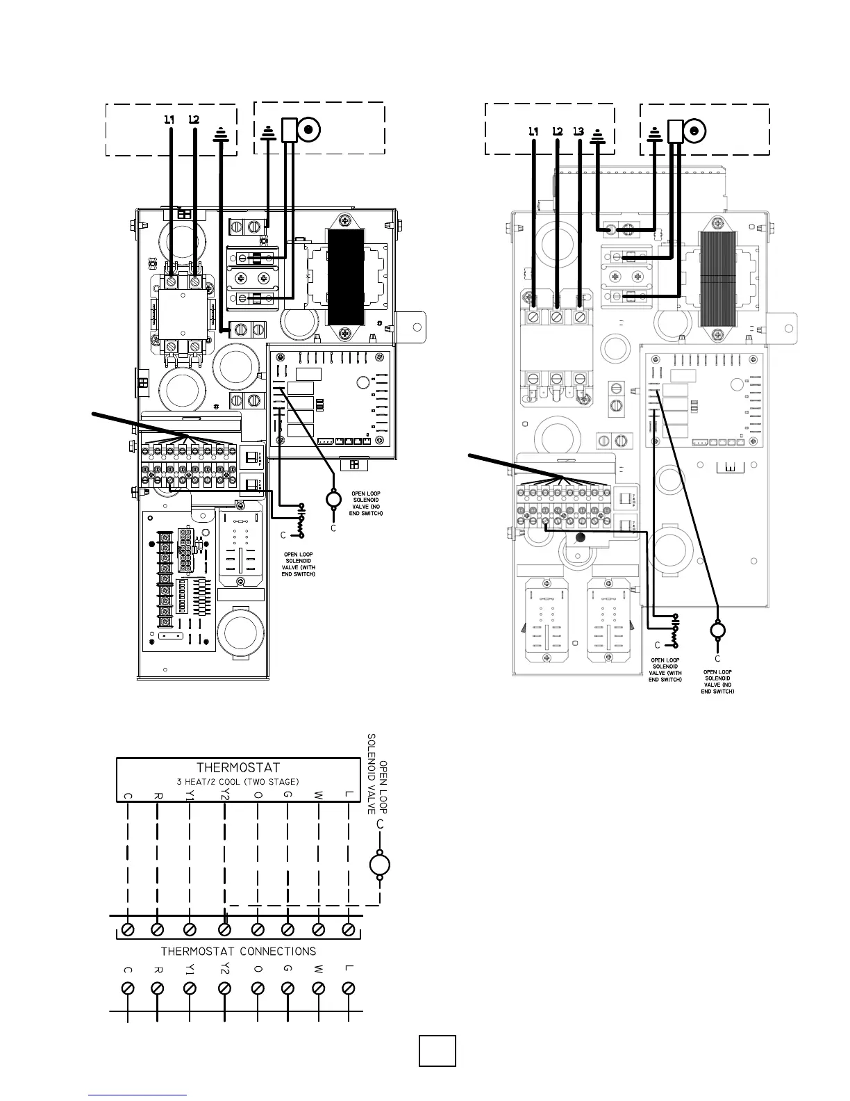
Single Phase Connections
Section 8: Electrical Connections
13S181−01NN
1
SHEET
Asm − Cont (VS LT)
208−230/60/1
SIGNIFICANT
CHARACTERISTICS
DO NOT SCALE
DRAWING
Asm − Cont (VS LT) 208−230/60/1
w/PumpBlock w/HWG Relay,ECM
PART DESCRIPTION
PART NAME
ENGINEER
SPECIFICATION
DATE
Matt Tripp
10/3/2014
OF
2
PART NUMBER
13S181−01NN
REV.
B
P
R
O
P
R
IET ARY AN
D
CO
N
FIDE NT IAL
THE INFORMATION CONTAINED IN THIS DRAWING IS THE SOLE
PROPERTY OF ENERTECH. ANY REPORDUCTION IN PART OR AS
A WHOLE, WITHOUT WRITTEN CONSENT, IS PROHIBETED.
◊
E NE R T E CH GL OB A L ,
L L C
2506 S. ELM STREET
GREENVILLE, IL 62246
(618) 664-9010
REVISION HISTORY
REV DESCRIPTION
ECN
DATE
APPROVED
~ ADDED SNAP BUSHING
10/3/2014 MATT TRIPP
A ADDED TWO HOLES FOR WIRE CLIPS
14−264−N03
10/15/2014
MATT TRIPP
B
UPDATE DRAWING FORMAT 14−315−N01
12/8/2014
MATT TRIPP
TERMINAL STRIP COVER REMOVED
WIRING ENTRY POINTS ON RIGHT FRONT CABINET CORNER POST
NOTES:
1. ALL BUSHINGS NEED TO BE PLACED ON THE CONTROL
BOX AND PLATE BEFORE OTHER ELECTRICAL COMPONENTS.
2. WIRING DIAGRAM
26
W
072−0
1NN SHOULD BE REFERENCED
FOR THIS ASSEMBLY.
BACK VIEW
HIGH AND LOW VOLTAGE
ELECTRICAL CONNECTIONS
WIRE CLIPS
100828 100828
11490000001
11490000001
11490000001
11490000001
11490000001
◊
1
◊
2
◊
3
L1 L2
Thermostat
External
Loop Pump
Power
Source
Connect to terminal A
Added Terminal A, Y1 notes 9-24-15 GT
Connect to terminal Y1
Three Phase Connections
Notes:
• Drawings represent a typical installation using wiring input
knockouts marked on the outside of the unit corner post.
• National and local electrical codes must be followed during
installation of this unit.
• Use caution to avoid damaging the wiring and components
during installation.
• Wiring shall be routed to avoid contact with other connec-
tions and temperature sensitive components.
• Assure all connections are securely fastened and routed to
their proper locations.
• Install the thermostat per the manufacturer’s instructions
provided with that unit.
FRONT VIEW
(WITHOUT TERMINAL STRIP COVER)
External
Loop Pump
L1 L2 L3
Power
Source
Thermostat
Connect to terminal A
Connect to terminal Y1
Added terminal A, Y1 notes 9-24-15 GT
Typical Thermostat Connections