32
Enertech Global IOM, VS/VT Models, Rev A
+
-
DC
Bridge
LED
Diode
RY1
24VAC input
from unit #1
+
-
Diode
RY2
24VAC input
from unit #2
RY1
RY2
240VAC input
240VAC to pump(s)
24VAC 24VAC
Figure 1: Board Layout
Figure 2: Board Schematic
240V IN
240V OUT
Relay Relay
240VAC
Power Source
240VAC
to Pump(s)
24VAC
connection
to unit #2
(Y1 & C From Thermostat)
24VAC
connection
to unit #1
(Y1 & C From Thermostat)
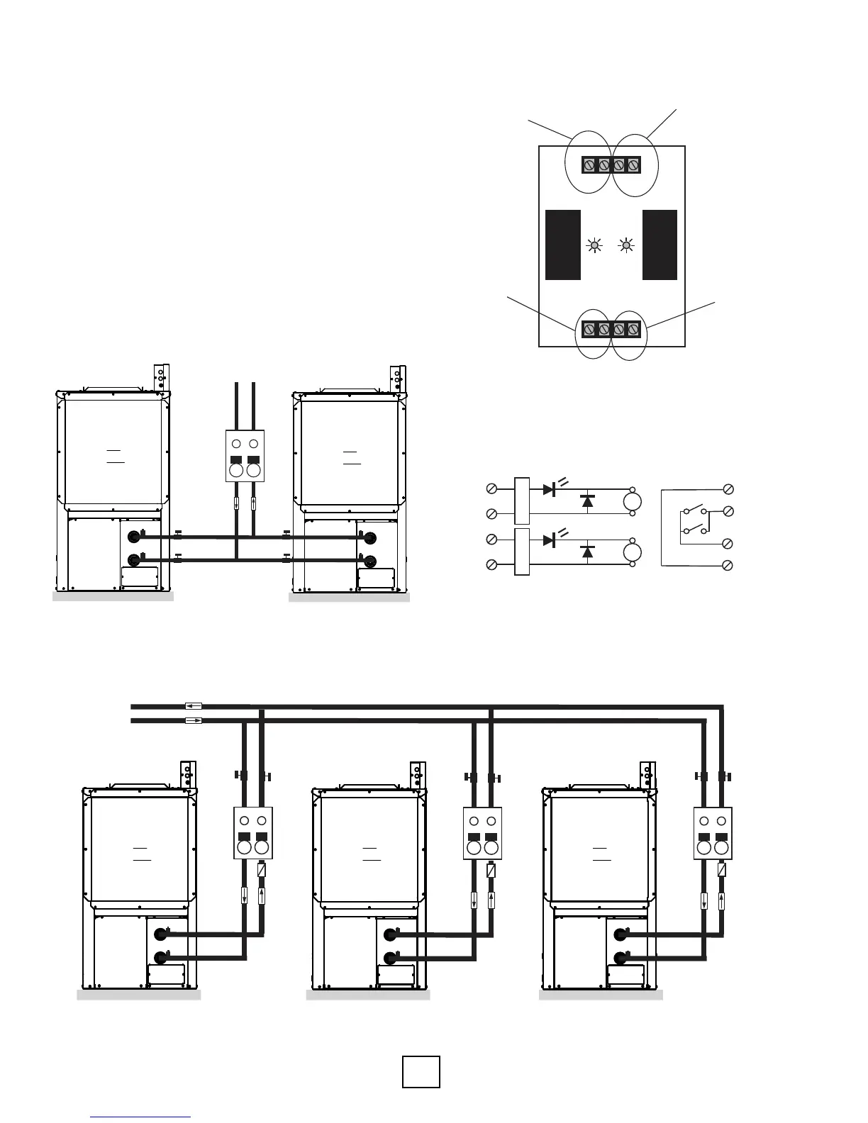
Figure 10: APSMA Module Layout
Figure 11: APSMA Module Wiring Schematic
APSMA Pump Sharing Module
The pump sharing module, part number APSMA, is
designed to allow two units to share one ow center.
With the APSMA module (Figure 10), either unit can
energize the pump(s). Connect the units and ow
center as shown in Figures 8 and 9, below.
Figure 11 includes a schematic of the board. The
module must be mounted in a NEMA enclosure or
inside the unit control box. Local code supersedes
any recommendations in this document.
Flow
Center
Hose
Kit
Loop Field
P/T Ports
air
coil
Source Out
Source In
P/T Ports
P/T Ports
air
coil
Source Out
Source In
P/T Ports
~
~
Shut O
Valves
Shut O
Valves
Equipment Pad
Equipment Pad
Flow
Center
Loop Field
P/T Ports
air
coil
Source Out
Source In
P/T Ports
~
Shut O
Valves
Flow
Center
P/T Ports
air
coil
Source Out
Source In
P/T Ports
Shut O
Valves
Flow
Center
P/T Ports
air
coil
Source Out
Source In
P/T Ports
Shut O
Valves
~
Check
Valve
Direction
of Flow
Check
Valve
Check
Valve
Direction
of Flow
Direction
of Flow
Direction
of Flow
Equipment Pad
Equipment Pad
Figure 8: Single Shared Flow Center, Dual Unit
Piping Example
Figure 9: Single Shared Loop Field, Individual Flow Center and Unit Piping Example
+
-
DC
Bridge
LED
Diode
RY1
24VAC input
from unit #1
+
-
Diode
RY2
24VAC input
from unit #2
RY1
RY2
240VAC input
240VAC to pump(s)
24VAC 24VAC
Figure 1: Board Layout
Figure 2: Board Schematic
240V IN
240V OUT
Relay Relay
240VAC
Power Source
240VAC
to Pump(s)
24VAC
connection
to unit #2
(Y1 & C From Thermostat)
24VAC
connection
to unit #1
(Y1 & C From Thermostat)
Section 5: Unit Piping Installation
Drawings represent typical unit installation, connection location,
type and appearance may differ per other models