43
IOM, VS/VT Models, Rev A Enertech Global
Section 9: Controls
Heating 3rd Stage, (Y1, Y2, W1, G) VT Units or
Heating 2nd Stage (Y1, W1, G) VS Units
When provided, the ECM fan remains at 100% of
2nd stage airow (CFM) level (based on DIP switch
settings), and the rst stage of electric resistance
heat is energized. Second stage of electric
resistance heat (W2) is energized ten minutes after
rst stage electric resistance heat (W1) is energized.
(W2 is only available with 10kW, 15kW and 20 kW
electric heaters)
Emergency Heat (W1, G) VT or VS Units
The fan is started immediately at 2nd stage airow
(CFM) level (based on DIP switch settings), and the
electric resistance heat is energized. Second stage
of electric heat (W2) is energized two minutes after
rst stage electric heat (W1) is energized. (W2 is
only available with 10kW, 15kW, and 20 kW electric
heaters)
Cooling Operation
The reversing valve is energized for cooling
operation. Terminal “O” from the thermostat is
connected to the reversing valve solenoid.
Cooling 1st stage (Y1, 0, G) VT or VS Units
The ECM fan immediately ramps up to 75% of 1st
stage (VT) or 2nd stage (VS) airow (CFM) level
(based on DIP switch settings), the Accessory (A)
terminal output is energized after the random start
timer (10s-20s) expires then rst stage compressor
and the loop pump(s) are energized 10 seconds
after “A”. The ECM fan adjusts to 100% airow
(CFM) level 90 seconds after the “Y1” input. VS units
with a PSC fan start at 100% airow (CFM) level
immediately upon the “G” input.
Cooling 2nd Stage (Y1, Y2, O, G) VT Units Only
The ECM fan adjusts to 2nd stage airow (CFM) level
(based on DIP switch settings), and the compressor
full load solenoid is energized.
Cooling, Dehumidication Mode VT or VS Units
When provided with an ECM fan motor, the
ECM fan control board includes two types of
dehumidication modes, Constant Dehumidication
mode, and On Demand Dehumidication (ODD).
If the ECM control board is set to Constant
Dehumidication mode, the ECM fan runs at normal
airow (CFM) in all heating stages, but all cooling
operation will be 85% of the current stage airow
(CFM) level (based on DIP switch settings). The
dehumidication mode lowers the airow (CFM)
through the evaporator coil, to improve latent
(dehumidication) capacity.
In ODD mode, a humidistat or a thermostat with a
dehumidication output (output must be reverse
logic -- i.e. it must operate like a humidistat) is
connected to the ODD terminal. When the module
receives a call for dehumidication, the fan runs at
85% of the current stage airow (CFM) in the cooling
mode. Otherwise, the airow is at the normal airow
(CFM) level. The signal is ignored in the heating
mode.
Fan Only VT or VS Units
When the ECM control module receives a “G”
call without a call for heating or cooling, the fan
operates at 50% of the full load airow (CFM) level
(based on DIP switch SETTINGS). VS units with a PSC
fan start at 100% airow (CFM) level immediately
upon the “G” input.
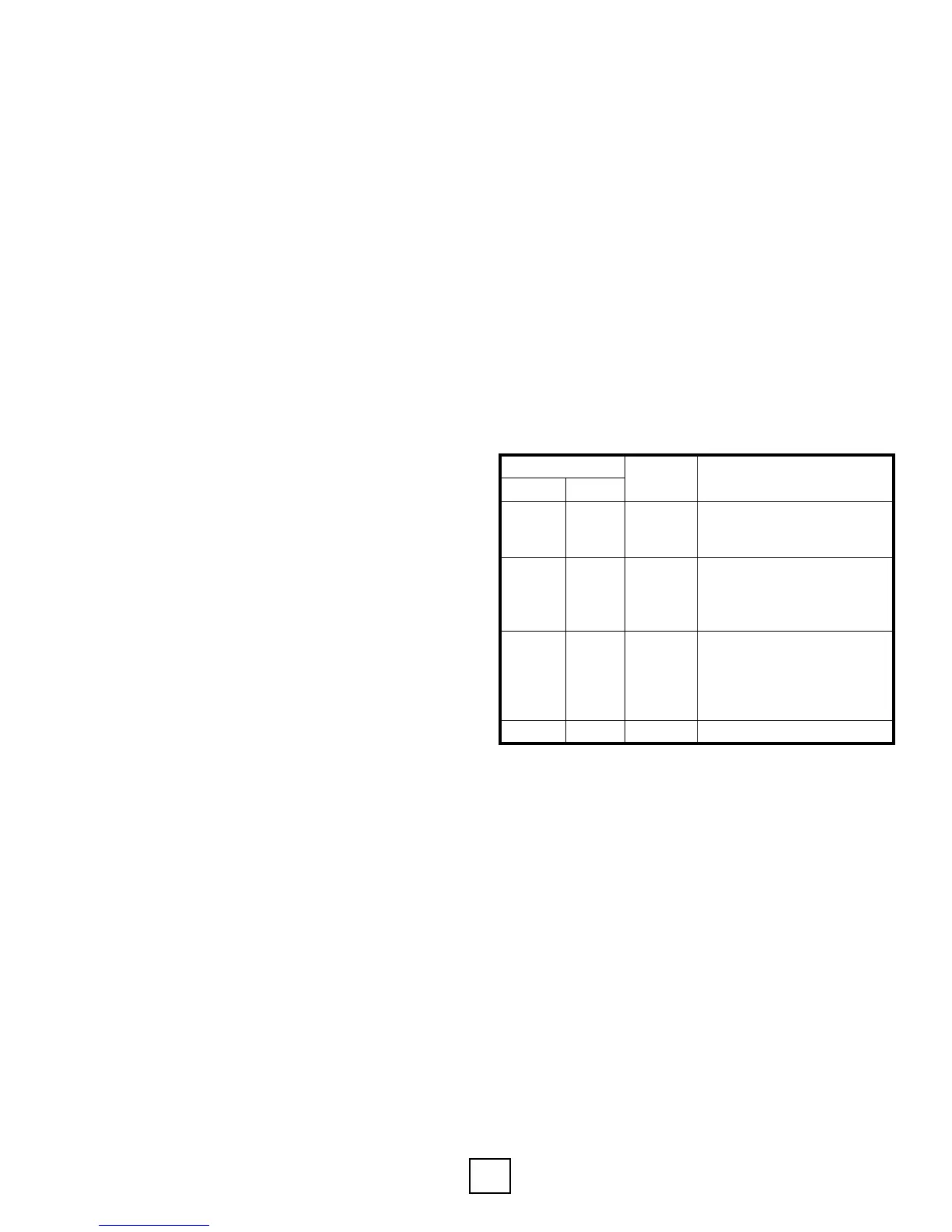
Dehumidication Mode Options
(ECM Fans Only)
DIP Switch
Mode Operation
S9 S10
ON OFF Normal
Dehumidication mode
disabled (normal Htg/Clg
CFM) - factory setting
OFF ON ODD
On Demand Dehumidication
mode (humidistat input at
terminal ODD) -
Humidistat required
OFF OFF
Constant
Dehum
Constant dehumidication
mode (always uses dehum
CFM for cooling and normal
CFM for heating) -
No humidistat required
ON ON Not Used Not an applicable selection
Notes:
1. To enter dehumidication mode, ODD input should be
0 VAC; for normal cooling CFM, ODD input should be
24VAC.
2. Heating CFM is not affected by dehumidication mode.
When in dehumidication mode, cooling CFM is 85% of
normal cooling CFM.