Illust. 7
Illust. 8 Illust. 9
Connecting the sensor lines
The connection cables to the temperature
sensor and power supply cables shall NOT
be drawn together or lead through the same
conduit. This can lead to interferences in the
electronics, such as „uttering“ in the relays.
If it is absolutely necessary to install them
together, or the wire is longer than 3 m, you
should use a shielded sensor line such as
the LIYLY-O x 0.5 mm²). Connect the shiel-
ding to mass in the control unit.
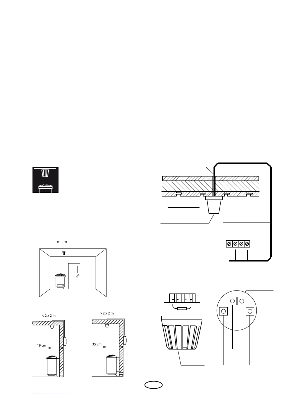
Please note that the following measure-
ments are based on values provided by
the unit quality assurance by the European
Standard EN 60335-2-53. In principle, you
must mount the oven sensor where tempe-
ratures are expected to be the highest. Il-
lust. 7 gives you an overview of the moun-
ting point of the sensor..
1. Mount the oven sensor in cabins up to 2
x 2 m according to Illust. 7 and 8, in larger
cabins according to Illust. 7 and 9.
2. Drill a hole to lead the cable through, pre-
ferably through the middle of one of the
wooden boards.
3. Lead the sensor cable through the drilled
hole and attach it to the sensor line accor-
ding to Illust. 10.
4. Attach the lines for the shutoff (white) and
the temperature sensor (red) according to
Illust. 11 to the sensor board. Then insert
the sensor board into the housing.
5. After you are nished installing and have
made sure the control unit is functioning
properly, check the line for overheat shut-
off protection for short circuits. To do this,
release one of the white lines in the sensor
housing. The safety relay of the control
unit should now fall; i.e. the heating circuit
should now be interrupted.
Hole
Sauna ceiling
Center sensor housing
on middle section
Sensor line
Terminals in the
control unit
Illust. 10
Housing
red
red
Sensor-
board
Illust. 11
Sensor
white (Limiter
white (Limiter)
Mounting the oven sensor