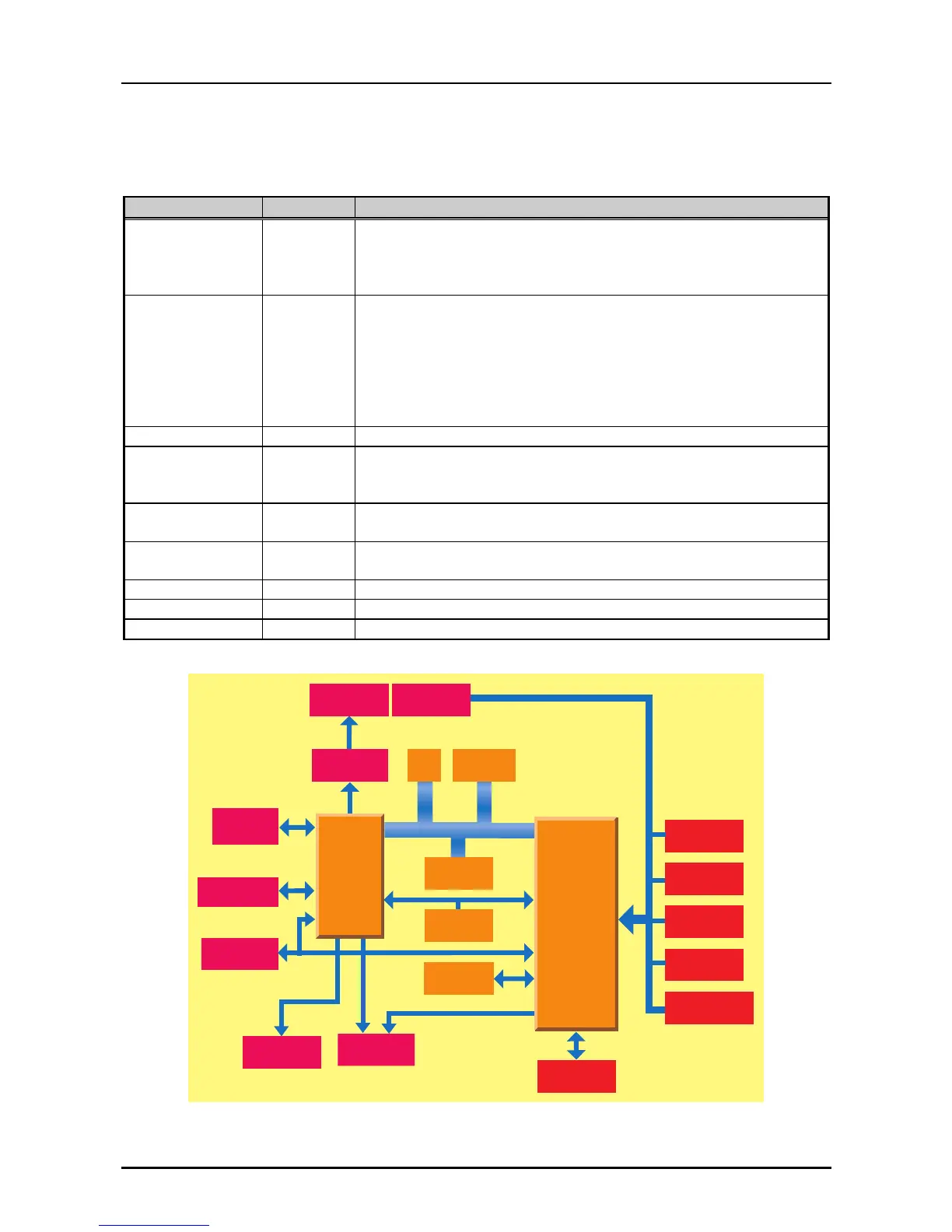
2.3.2 C229MAIN Board Circuit
The C229MAIN board is the control circuit board of this printer. This board consists of several IC
chips and drivers, as shown in the table below:
Table 2-3. Function of the Main IC
Element Location Function
TMP96C141AF IC3 16 bit CPU runs at 14.47MHz
- Main controller
- Detectors control
- CR Motor Control
E05B50 IC2 Gate array : System Controller
- Parallel I/F control
- Option Type-B I/F control
- Panel Switch, LED control
- Printhead Control
- PF Motor Control
- CR Motor Current control
PST594E IC1 Reset IC : Hardware reset function
AT93C46 IC4 EEPROM :
System control data (Market, TTL threshold, Bi-D setting, Page
length, TOF, etc.) containing
PSRAM IC5 1M/4M bit
- Buffer and Working area of CPU & Gate array
ROM IC7 2/4M bit EPROM/ Mask ROM
- Control program containing
SLA7024M IC8 CR Motor driver
A2917SEB IC11 PF Motor driver
Comparator IC12 Power-off signal sensing
EEPRO M
P a ra lle l I/F
Type-B I/F
(O ption)
O peration
Panel
PF M otor
Driver
CR Motor
Driver
Head Driver
P rinthead
HP Detector
R elease
Lever D etector
P G D e te c to r
Rear
PE Detector
Front
PE Detector
+35V D etector
ROM
Addres/DATA Bus
CG
PSRAM
Therm istor
G.A.
E 05B 50
(IC 2 )
CPU
TM P 96C 01A F
(IC 3 )
R e s e t IC
Figure 2-5 . C229MAIN Board Circuit Block Diagram