5.2.3 Bi-D Adjustment
Bi-D adjustment can be made either through the panel operation or with the adjustment program.
This section describes Bi-D adjustment performed with the following program:
1. Connect the printer and the PC by a parallel interface cable.
2. Set 10-inch-wide continuous paper to the printer.
3. Run the adjustment program in the host computer.
4. Select the printhead wire. (Refer to 5.2.2.)
5. Select the market setting. (Refer to 5.2.2.)
6. Select the carriage width. (Refer to 5.2.2.)
7. The main menu appears. Move the cursor using “↑” or “↓” key to select “
(1) Bi-D Adjust
” from
the list and press “
Return
” key, and the test pattern printing starts.
8. Then the Bi-D adjustment menu appears. Move the cursor using “↑” or “↓” key to select Bi-D
printing mode from the three printing modes and “←” or “→” key to change the setting value.
9. Press “
Space
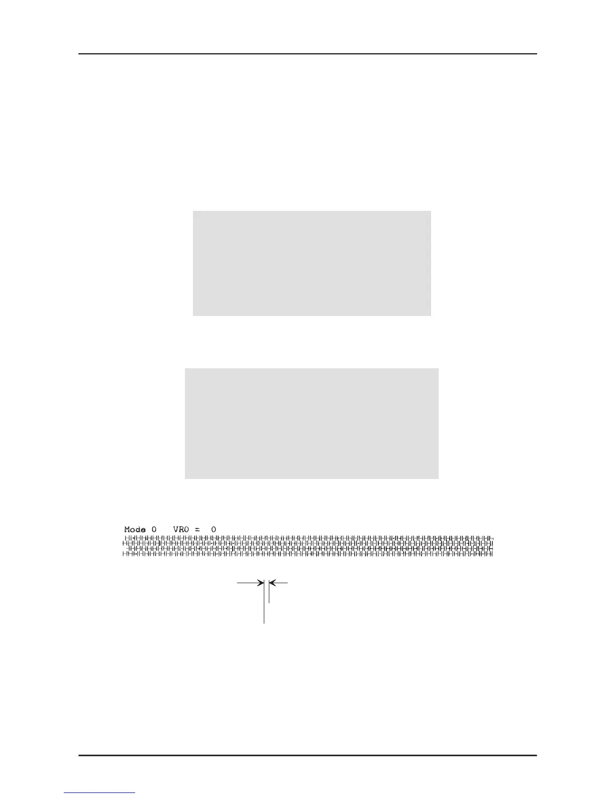
” key, and a Bi-D pattern in four tiers for the current setting print mode and the
value shown below are printed:
H
H
a
Figure 5-4. Bi-D Adjustment Pattern
Program : xxxxx Setting:
9 pins VR 0 = x VR 1 = x VR 2 = x
** In line**
[ Main Menu ]
>(1) Bi-D Adjust (6) Envelope
(2)FF paper (7) – SUB MENU
(3) ---- N/A ----
< Bi-D Adjustment >
> Mode 0 = x
Mode 1 = x
Mode 4 = x
Cancel Print Speed Value Write Default
[ESC] [SPACE] [↑ ↓][←→] [RET] [HOME]