4.2.10.8 Carriage Assembly Removal
1. Remove the printer mechanism. (See Section 4.2.9.)
2. Remove the Head FFC. (See Section 4.2.1.)
3. Remove the Platen. (See Section 4.2.8.)
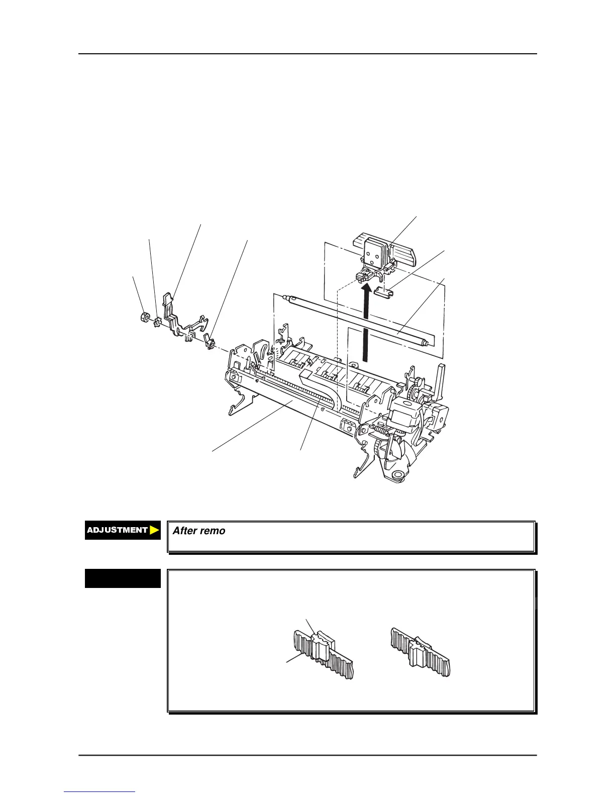
4. Remove the hexagon nut and the washer securing the LEVER,G,ADJUST to the
SHAFT,CR,GUIDE, and remove the lever.
5. Remove the BUSHING,PARALLEL,ADJUST to turn the SHAFT,CR,GUIDE.
6. Disengage the TIMING BELT from the CR motor. (See Section 4.2.10.1.)
7. Move the carriage assembly to the right end, and remove it from the rack of the
FRAME,FRONT with the SHAFT,CR,GUIDE.
8. Release the TIMING BELT from the 2 clips at the bottom of the carriage assembly.
C arriage A ssem bly
OIL PAD
SHAFT,CR,GUIDE
BUSHING,PARALLEL,ADJUST
LEVER,G ,ADJUST(Release Lever)
H exagon N ut
Washer
TIM ING BELT
FRAM E,FRONT
Figure 4-19. Carriage Assembly Removal
$'-8670(17
After removing the carriage assembly, perform the Platen Gap
adjustment and Bi-d adjustment. (See Chapter 5.)
CHECK POINT
9
When attaching the TIMING BELT to the carriage assembly, secure the
TIMING BELT with the left and right clips in the carriage assembly, as
shown below, and ensure there is no slack in the TIMING BELT.
Clip
<N G >
<O K >
TIM IN G BELT
Figure 4-20. Attaching the TIMING BELT