4.2.9 Printer Mechanism Removal
1. Remove the PAPER GUIDE ASSEMBLY, top cover, front cover, paper eject cover, knob and
tractor unit. (See Section 4.2.3.)
2. Remove the upper housing. (See Section 4.2.4.)
3. Remove 5 CBS (M3 × 4) screws and 3 CBB (3 × 12) screws securing the shield cover to the
printer mechanism and lower housing. Then remove the shield cover. (See Figure 4-6. )
4. Disconnect the harnesses from the connectors CN3, CN4, CN5, CN6, CN7, CN8, CN9, CN10
and CN11 on the C229MAIN board.
5. Remove 2 CBB (4 × 12) screws securing the front frame to the lower housing, and remove
the front frame.
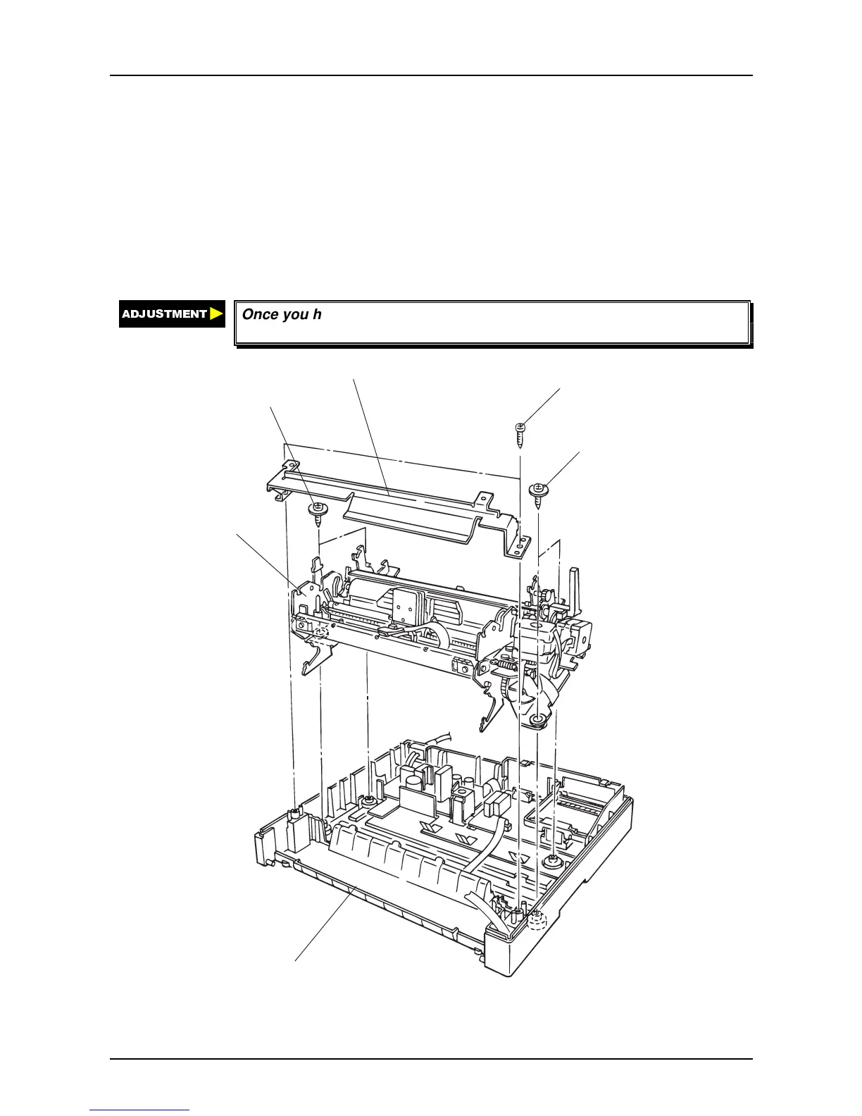
6. Remove 4 mechanism fixing screws, and remove the printer mechanism by lifting it up.
$'-8670(17
Once you have removed the printer mechanism, be sure to perform the
platen gap and the Bi-D adjustment.
CBB(4 x 12)
M echanism Fixing Screw
M echanism Fixing Screw
Front Fram e
Printer M echansim
Low er H ousing
Figure 4-9. Printer Mechanism Removal