4.2 DISASSEMBLY AND ASSEMBLY
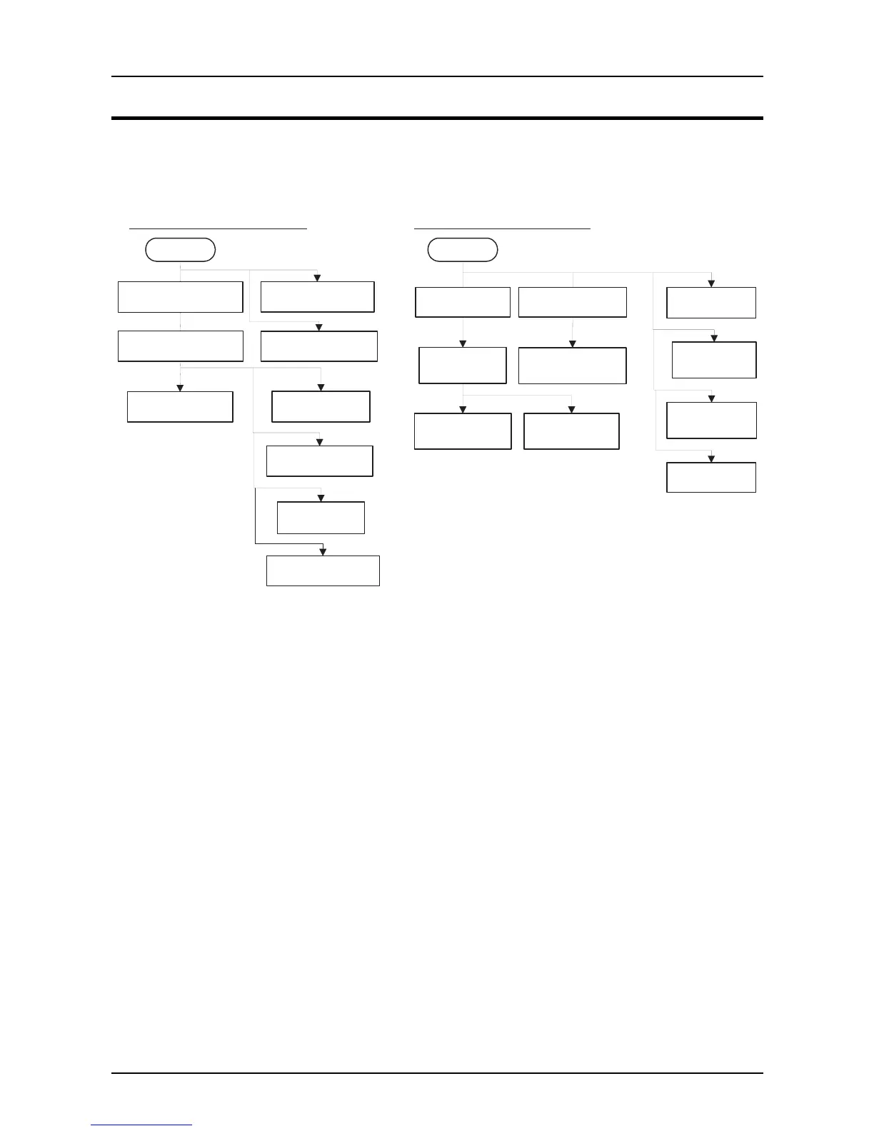
This section provides the disassembly procedures. The basic order for disassembly is shown in
the flowchart below. The exploded diagrams are also provided in the APPENDIX. Refer to them to
see how components are engaged each other if necessary.
START
P re-disassem bly
Procedures
Printhead R em oval
U pper H ousing R em oval
HP Detector Rem oval
P r in te r M e c h a n is m
Removal
C 229M AIN B oard
Removal
C229PSB/PSE/PSH
Board Rem oval
Platen Rem oval
P F M o to r R e m o v a lCR Motor Rem oval
P G D e te c to r
Removal
Release Detector
Removal
F ro n t P E D e te c to r
Removal
Rear PE Detector
Removal
C arriage A ssem bly
Removal
PF G ear Train R em oval
R ibbon D rive
A ssem bly R em oval
R ear P aper G uide
A ssem bly R em oval
Printer M echanism D isassem bly
START
M ain C om pornents D isassem bly
ROM Replacem ant
Figure 4-1. Disassembly Flowchart