2.3 CIRCUIT OPERATION
2.3.1 C229PSB/PSE/PSH Power Supply Circuit
This printer can be powered by one of the following three power supply boards: the C229PSB
(120V) board, the C229PSE (230V) board, or the C229PSH (Universal) board. The function of the
boards is the same , except for a difference in the primary circuitry. The power supply outputs the
DC current necessary to drive the printer control circuit and drive the mechanism. The input
voltages and fuse ratings are as shown in the following table:
Table 2-1. Input Voltage and Fuse Rating
Board Input Voltage Fuse F1 Rating
C229PSB 85-138VAC 4A, 125V or 250V
C229PSE 187-276VAC T2.0AH, 250V
C229PSH 85-276VAC T4.0AH, 250V
The power supply circuit outputs voltages used to drive the various control circuits and the
mechanism, as shown in the following table:
Table 2-2. Output Voltages and Applications
Output Voltage Applications
5V
p
5% 0.7A Logic lines
(Type-B I/F output is included.) Detectors
Panel Switches & LEDs
35V
p
6% 0.8A CR Motor
PF Motor
Printhead
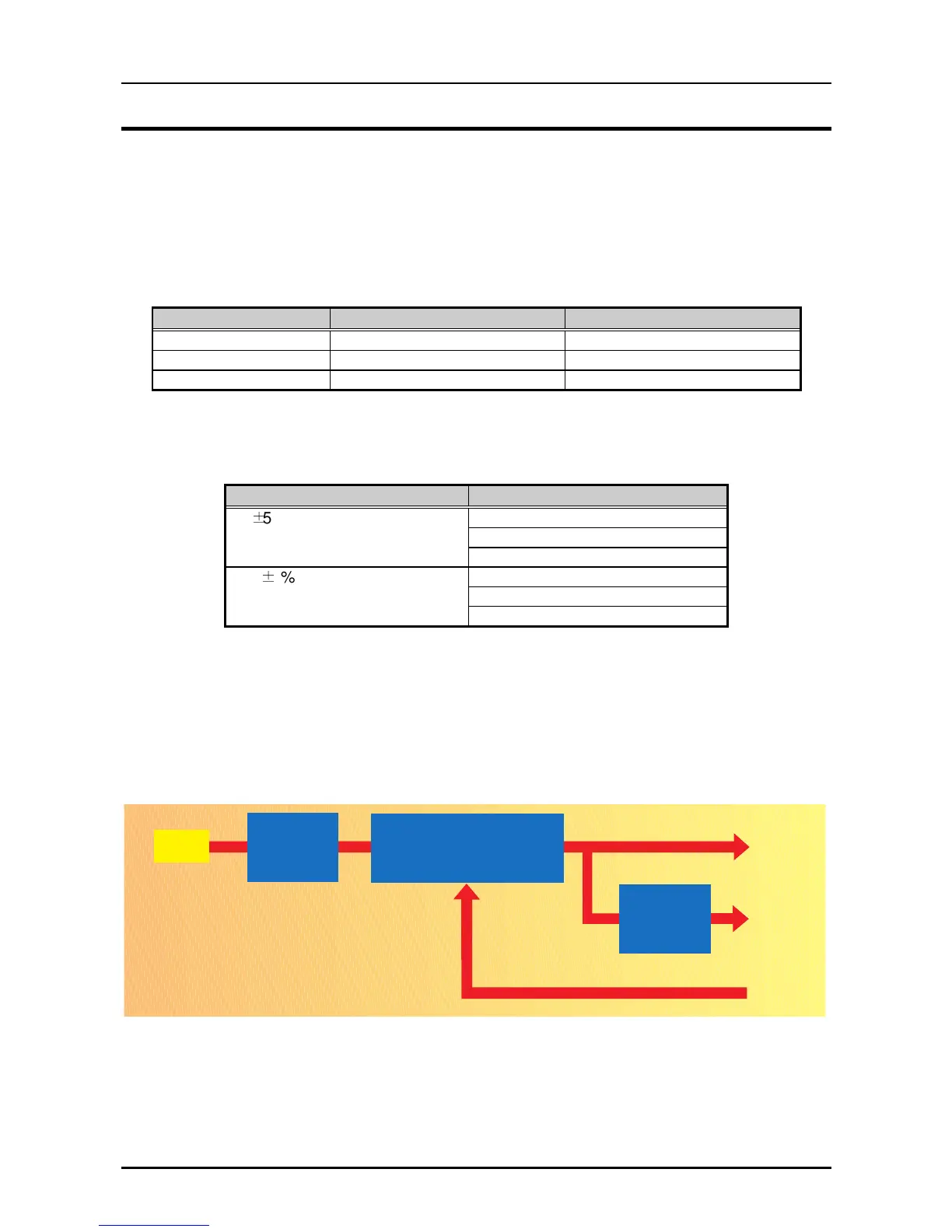
The power supply circuit consists of the line filter circuit, ZC-RCC (Zero-Cross Ringing Choke
Converter) switching circuit and 5V chopper regulator IC. The AC voltage is first input to the line
filter circuit for higher harmonics absorption, then input to the switching circuit and transformed to
+35VDC. +5VDC is generated from +DC35V by the regulator IC. The over current / voltage
protection circuit is also designed on the board.
The power switch set in the secondary circuit that is controlled by the signal PSC from the control
panel.
Line Filter
ZC-RCC Switching Regulator
AC Line
In p u t
+35V D C
+5VD C
PSC
- O ver C urrent protection
- O ver V oltage protection
R e g u la to r IC
Figure 2-4. Power Supply Circuit Block Diagram