FX-1180/FX-880 Service Manual
Appendix
Rev. B
7-1
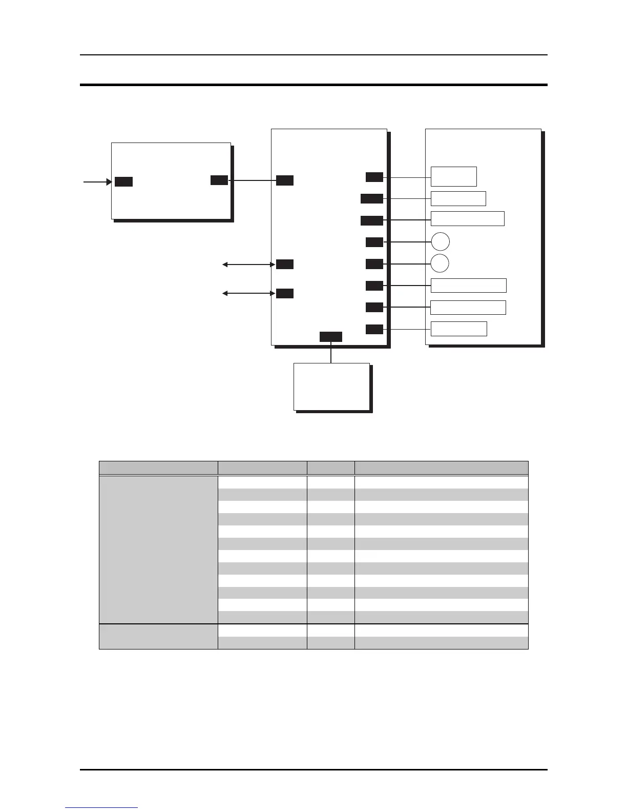
7.1 CONNECTOR SUMMARY
The primary components of the printer are connected as shown below;
C229PSB/PSE/PSH Board
AC
C229M AIN Board
Panel
CN1
CN2
CN3
CN1
CN2
Printer M echanism
M -3J60(FX -1180)
M -3J10(FX -880)
CN12
P a ra lle l I/F
Type-B I/F
CN4
CN5
CN6
CN7
CN8
CN9
CN10
CN11
Printhead
P G D e te c to r
R elease D etector
CR Motor
P F M o to r
Rear PE Detector
Front PE D etector
HP Detedtor
Figure 7-1. Cable Connections
Table 7-1. Connector Summary
Board Connector No. Pin Description
C229MAIN Board CN1 36 Parallel I/F
CN2 36 Type-B I/F (Option)
CN3 10 DC input, Power On/Off
CN4 2 HP Detector
CN5 3 Rear PE Detector
CN6 2 Front PE Detector
CN7 16 Printhead, Thermistor
CN8 4 PF Motor
CN9 5 CR Motor
CN10 2 Release Detector
CN11 2 PG Detector
CN12 12 Panel
C229PSB/PSE/PSH CN1 2 AC line input
Board CN2 10 DC output