4.2.5 C229MAIN Board Removal
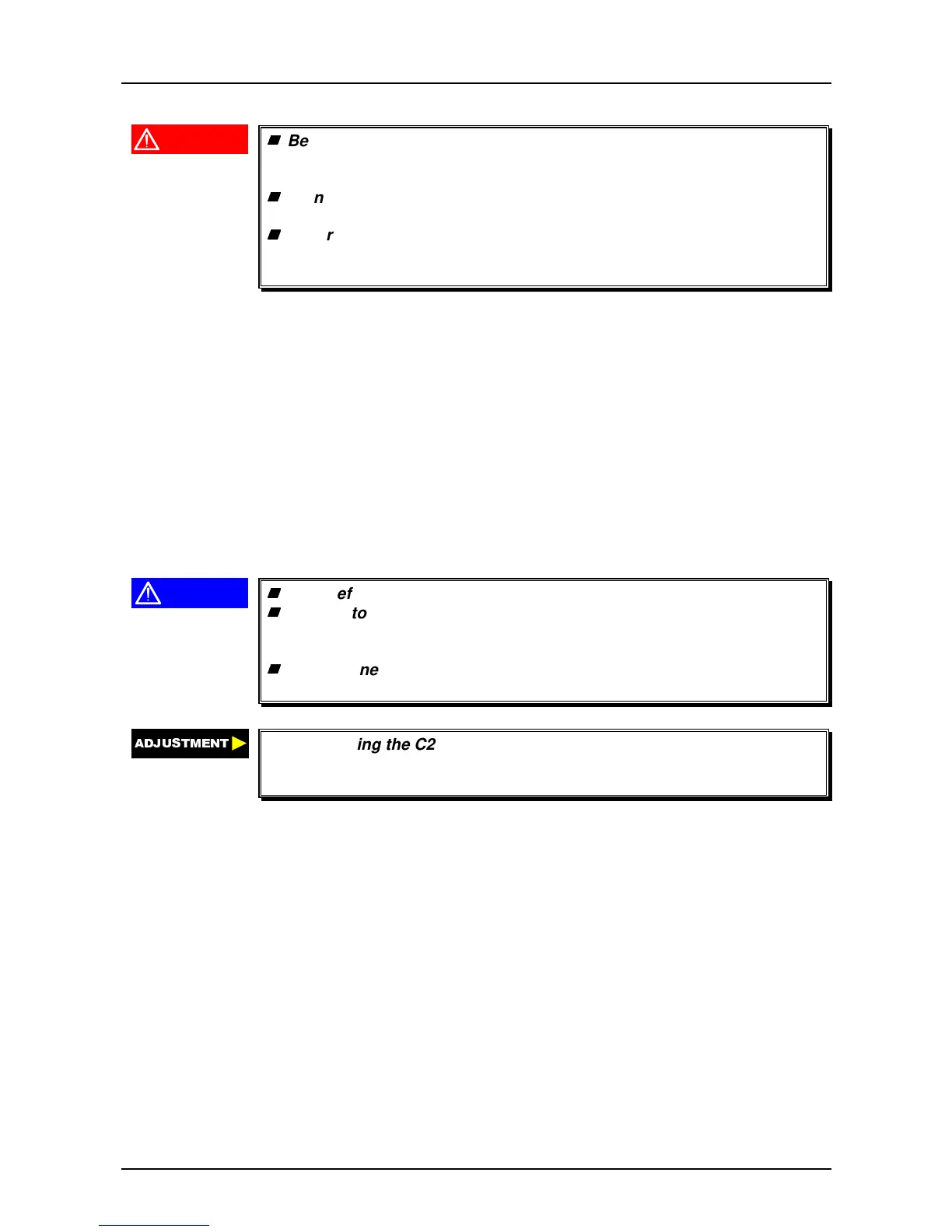
WARNING
Before disassembling, assembling or adjusting the printer,
disconnect the power supply cable from the AC power socket.
Failure to do so might cause personal injury.
Do not touch the heat sink attached to the switching FET (Q1) on the
power supply board right after power off, as it may be very hot.
Never touch the heat sink attached to the switching FET (Q1) while
The AC power cable is connected to the AC outlet, as it is not
electrically isolated.
1. Remove the PAPER GUIDE ASSEMBLY, top cover, front cover, paper eject cover, knob and
tractor unit. (See Section 4.2.3.)
2. Remove the upper housing. (See Section 4.2.4.)
3. Remove 5 CBS (M3 × 4) screws and 3 CBB (3 × 12) screws securing the shield cover to the
printer mechanism and lower housing. Then remove the shield cover.
4. Disconnect the harnesses from the connectors CN3, CN4, CN5, CN6, CN7, CN8, CN9,
CN10, CN11 and CN12 on the C229MAIN board.
5. Remove 2 CBS (M3 × 12) screws securing the COVER,CONNECTOR,UPPER to the I/F
GROUNDING PLATE.
6. Remove 6 CBB (3 × 12) screws securing C229MAIN Board to the lower case.
7. Remove the GUIDE, I/F BOARD and GROUNDING PLATE,I/F,UPPER.
8. Remove 2 CP (M3 × 8) screws securing the I/F GROUNDING PLATE to the C229MAIN
board. Then remove the I/F GROUNDING PLATE.
CAUTION
Be careful with the edges of the shield plate, as they are very sharp.
Be sure to match the connector colors with each other. However, the
yellow harness must be connected to CN10, and the blue harness
must be connected to CN11.
The red line sides of the harnesses for CN3, CN8 and CN9 must be
set to No.1 pin side.
$'-8670(17
After replacing the C229MAIN Board, perform the Default setting and Bi-
d adjustment to store the new data into the EEPROM on the main board.
(Refer to Chapter 5.)