EasyManua.ls Logo

Epson RX4111CE - Wake-Up Timer Interrupt Function; Related Registers for Function of Wake-Up Timer Interrupt Function; Table 19 Wake-Up Timer Interrupt Register; Table 20 TSEL Bit Source Clock Select

Epson RX4111CE
61 pages
Print Icon
To Next Page IconTo Next Page
To Previous Page IconTo Previous Page
Loading...
14. How to use
RX4111CE Jump to Top / Bottom
ETM62E-02 Seiko Epson Corporation 27
14.2. Wake-up Timer Interrupt Function
s
31.9 years
tRTN2 after the interrupt occurs, the /INT status is automatically released (/INT status changes from
low-level to Hi-z).
14.2.1. Related Registers For Function Of Wake-up Timer Interrupt Function
Table 19 Wake-up Timer Interrupt Register
Bank1
Address[h]
Function
bit 7
bit 6
bit 5
bit 4
bit 3
bit 2
bit 1
bit 0
A
Timer Counter 0
128
64
32
16
8
4
2
1
B
Timer Counter 1
32768
16384
8192
4096
2048
1024
512
256
C
Timer Counter 2
8388608
4194304


524288

131072
65536
D
Extension Register
FSEL1
FSEL0
USEL
TE
WADA
TSEL1
TSEL0
E
Flag Register
POR
z
UF
TF
AF
EVF
VLF
XST
F
Control Register
z
z
UIE
TIE
AIE
EIE
z
STOP
Bank2-D
Timer Control
z
z
z
z
TBKON
TBKE
TMPIN
TSTP

Wake-up timerWake-up Timer Counter0,1 register can be used as a
RAM register. In such cases, stop the Wake-up timer function by writing 0 to the TE and TIE bits.
1) Down counter for Wake-up timer (Timer Counter )
This register is used to set the default (preset) value for the counter. Any count value from 1to 16777216can be set.
Be sure to write 0 to the TE bit before writing the preset value.




2) TSEL1, TSEL0 bit
The combination of these three bits is used to set the countdown period (source clock) for this function.
Table 20 TSEL bit Source Clock Select
TSEL1
(bit 1)
TSEL0
(bit 0)


 
0
0
Hz
s
 s
0
1
Hz

ms
1
0
Hz

ms
1
1
Hz

ms
1) The /INT pin's Auto reset time (tRTN2) varies as shown above according to the source clock setting.
2) The first countdown shortens than a source clock.
When selected 4096 Hz / 64 Hz / 1 Hz as a source clock, one period of error occurs at the maximum.
When selected 1/60 Hz, 1 Hz of error occurs at the maximum.
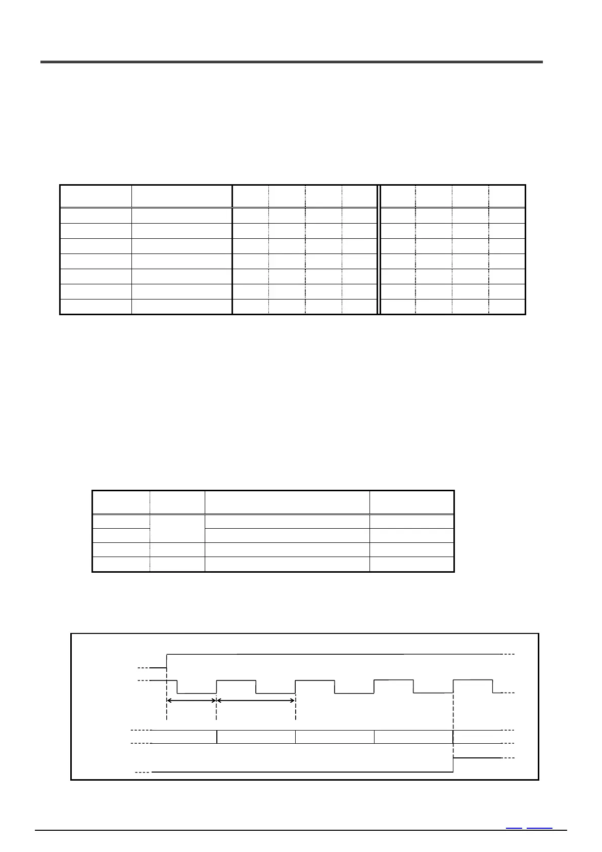
The example of the error of the first countdown: A preset value is 04h.
Cycle error
初回周期誤差
TE
Designated cycle
Internal source clock
TF Flag  
TF
3
2
1
4
Down counter
4
Figure 20 Wake-up Timer Initial Sequence (cycle error)

Table of Contents

Related product manuals