EasyManua.ls Logo

Epson RX4111CE - Battery Backup Switchover Function; Description of Battery Backup Switchover Function; Table 44 Battery Backup Switchover Function Related Register; Table 45 INIEN Bit (Initial Enable)

Epson RX4111CE
61 pages
Print Icon
To Next Page IconTo Next Page
To Previous Page IconTo Previous Page
Loading...
14. How to use
RX4111CE Jump to Top / Bottom
ETM62E-02 Seiko Epson Corporation 39
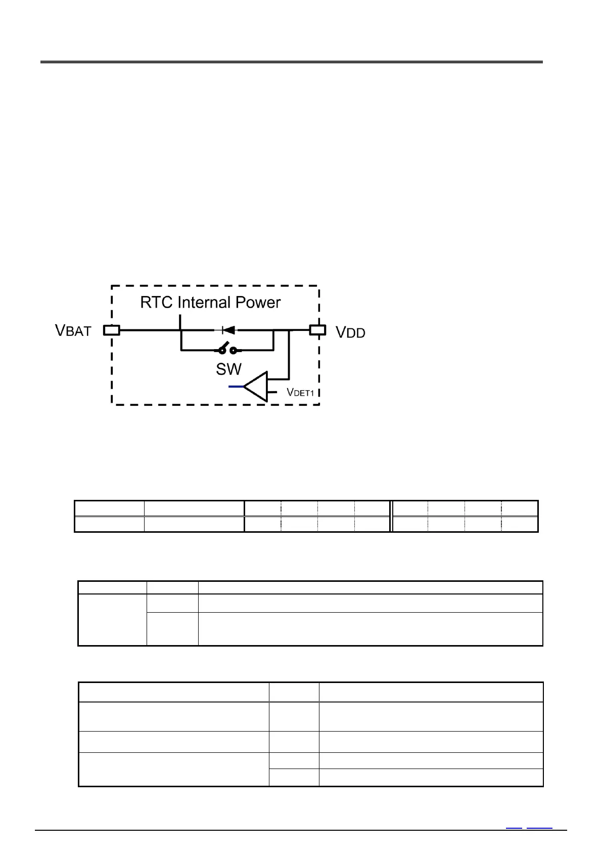
14.7. Battery Backup Switchover Function
14.7.1. Description of Battery Backup Switchover Function
This function can detect voltage drop of V
DD
and switchover power supply from V
DD
to V
BAT
. This function circuit
comprises the comparator detector VDET which detect the power down of the main power source "VDD", and built-in
MOS switch (SW) and a diode located between the main power-source pin "VDD" and the backup power supply pin
"VBAT". Refer to Figure 28.
By switching SW according to the result of the supply-voltage detection of VDET1, the RTC power supply is changed from
V
DD
. Also, the diode protects reverse current from V
BAT
to V
DD
.
There are two modes depend on power supply status.
1) Normal mode: RTC power supply from V
DD
2) Backup mode: RTC power supply from V
BAT
During backup mode, FOUT becomes Hi-Z status, SPI-Bus is inactive, signal lines are floating.
When the VLF bit detects 0 1, the default value of backup battery switchover function related registers is set.
Figure 29 Battery Backup Switchover Function Block Diagram
14.7.2. Related Register of Battery Backup Switchover Function
Table 44 Battery backup switchover function related register
Address[h]
Function
bit 7
bit 6
bit 5
bit 4
bit 3
bit 2
bit 1
bit 0
Bank3 - 2
Power Switch Control
INIEN
z
z
SWSEL1
SWSEL0
SMPT1
SMPT0
1) INIEN bit
Control of MOS-Switchover function ON/OFF.
Table 45 INIEN bit (Initial Enable)
INIEN
Data
Description
Write / Read
0

1
    
If V
DD
voltage drop is detected SPI-Bus communication is switched OFF and
signals are floating.
2) SW status
Table 46 SW status
State
SW
Description
Power supplied from V
BAT
first then V
DD
supply
OFF
Power supplied diode OR of V
DD
and V
BAT
.
Power supplied from V
DD
first then V
BAT
supply
OFF
Power supplied from V
DD
via diode first then Power
supplied diode OR of V
DD
and V
BAT
.
Battery backup switchover function: ON
INIEN bit = 1
ON
V
DD
= ON: Normal mode
OFF
V
DD
= OFF: Backup mode

Table of Contents

Related product manuals