SC-F9200 Series Revision B
DISASSEMBLY & ASSEMBLY Disassembly and Assembly Procedure 119
SE Group Confidential (Related Staff Only)
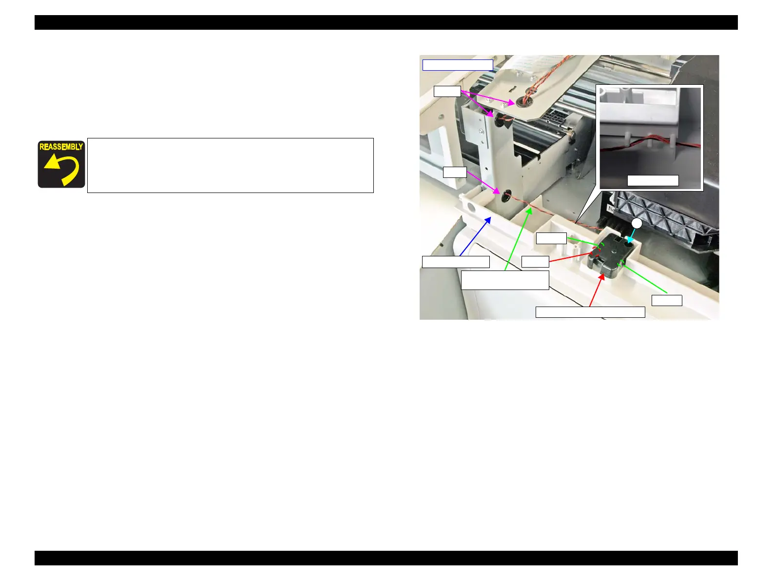
8. Remove the screw that secures the R Maintenance Cover Sensor.
A) Silver M3x8 P-tite screw with built-in washer: 1 pcs
9. Pull out the cable through the three holes on the frame.
10. Release the cable from the cable guide of the Right Front Cover, and remove the R
Maintenance Cover Sensor.
Figure 3-40. Removing the R Maintenance Cover Sensor
When installing the R Maintenance Cover Sensor, properly
engage its two dowels and one hook with the three positioning
holes on the Right Front Cover.
Route the sensor cable through the cable guide correctly.
- Right front side -
Holes
Hole
R Maintenance Cover
Sensor Cable
R Maintenance Cover Sensor
Right Front Cover
Dowel
Hook
Dowel
A

 Loading...


