SC-F9200 Series Revision B
DISASSEMBLY & ASSEMBLY Disassembly and Assembly Procedure 201
SE Group Confidential (Related Staff Only)
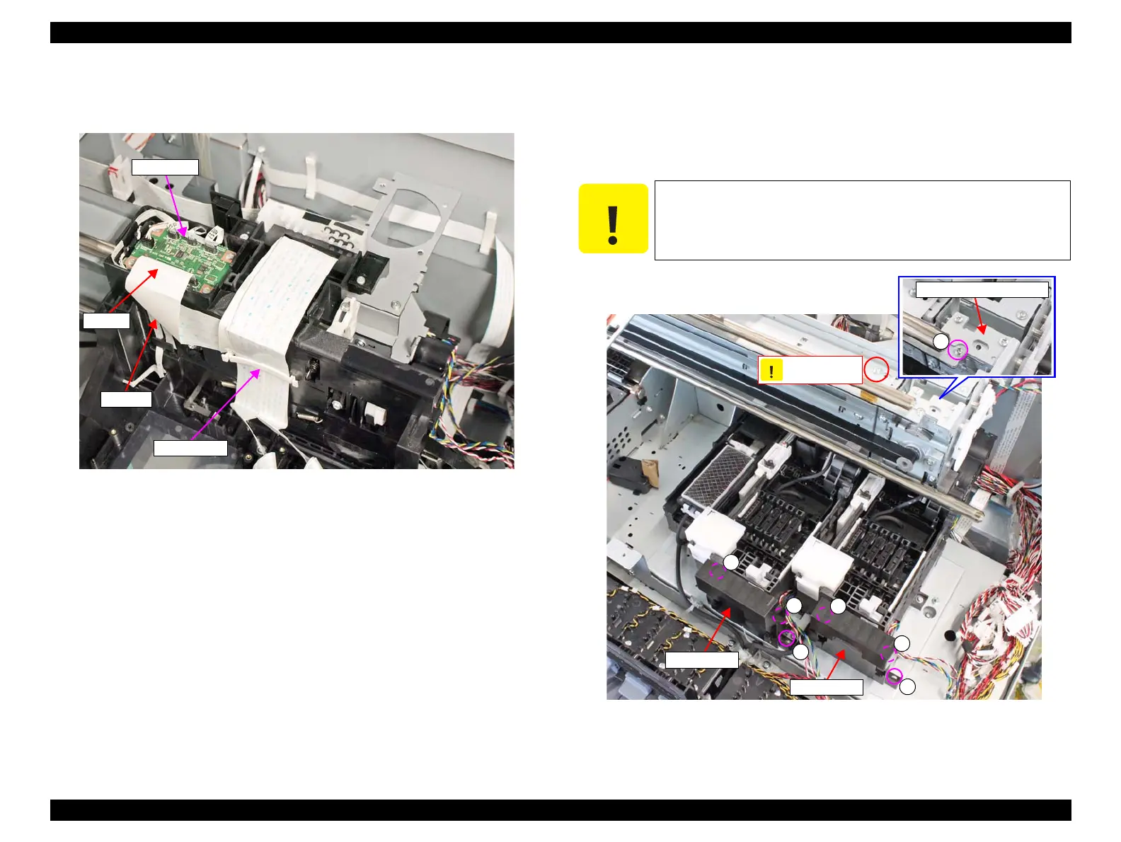
16. Disconnect the CR FFC from the connector (CN100) on the Sub Board.
17. Remove the FFC clamp that secures the Head FFCs.
Figure 3-144. Removing the Ink Path Holder Assy
18. Remove the six screws, and remove the two CR Stopper.
C) Silver M3x8 screw: 6 pcs
19. Remove the screw, and remove the CR Scale Mounting Plate.
D)Silver M3x6 Cup S-tite screw: 1 pcs
Figure 3-145. Removing the CR Stopper
Sub Board
CR FFC
FFC Clamp
CN100
Never remove or loosen the screw shown below.
CR Stopper
Never remove!
CR Stopper

 Loading...


