SC-S30600 Series Revision B
DISASSEMBLY & ASSEMBLY Disassembly and Assembly Procedure 97
Confidential
3.4.3.8 Left Front Cover/L Maintenance Cover Sensor
1. Remove the Left Rear Cover. (p94)
2. Remove the Left Upper Cover. (p95)
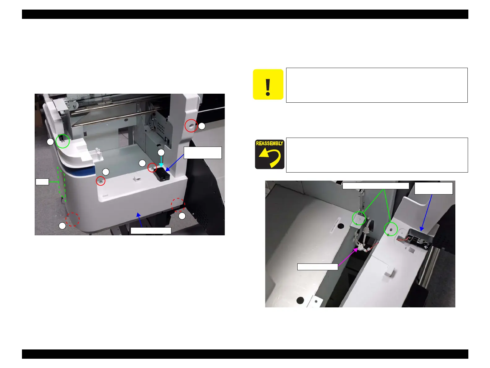
3. Remove the screw, and remove the L Maintenance Cover Sensor.
A) Silver M3x10 P-tite screw with washer: 1 pcs
Figure 3-32. Left Front Cover/L Maintenance Cover Sensor Fixing Screws
4. Remove the six screws that secure the Left Front Cover.
B) Silver M4x10 S-tite screw with washer: 5 pcs
C) Silver M4x12 P-tite screw with washer: 1 pcs
5. Slide the Left Front Cover toward the front of the printer.
6. Disconnect the cable of the L Maintenance Cover Sensor from the relay connector.
Figure 3-33. Removing the Left Front Cover
A
C
B
B
B
B
B
L Maintenance
Cover Sensor
Left Front Cover
Tabs
At the next step, be careful not to pull the Left Front Cover too
much as the cable of the L Maintenance Cover Sensor is connected
to the relay connector.
Insert the two tabs of the Left Front Cover into the two
positioning holes on the Left Cover.
Insert the two dowels of the frame into the two positioning
holes on the Left Front Cover.
L Maintenance
Cover Sensor
Positioning holes and dowels
Relay Connector
 Loading...