1 TEST PROGRAMS AND ADJUSTMENTS58 / 266
Adjustment 2
Power supply unit output parameters
Procedure
• Connect 500 ohms load resistance (APM 600) to MP1 = GND and MP2 = +U on “Power Module”
board (slot J5).
• Plug in the power cable on the ICC.
• Call up Test program 16, Adjustment 2.
• Activate ERBOTOM ICC using the yellow footswitch pedal (AUTO CUT).
• Set TP2 on the control board (slot J3) in such a way that 100 W (tolerance +0% / –7%) can be
measured at the HF power meter and a power supply current of 447 mA (tolerance 444...455 mA) is
displayed in the AUTO COAG 1 display. In the AUTO CUT display, a power supply voltage of 223
V (tolerance 223…227 V) is displayed.
• Disconnect the ICC from the power and remove the connecting cable from MP1 and MP2.
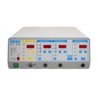
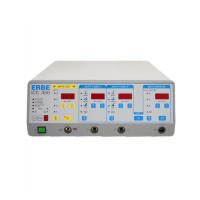
ICC 350
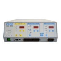
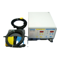
ICC 300
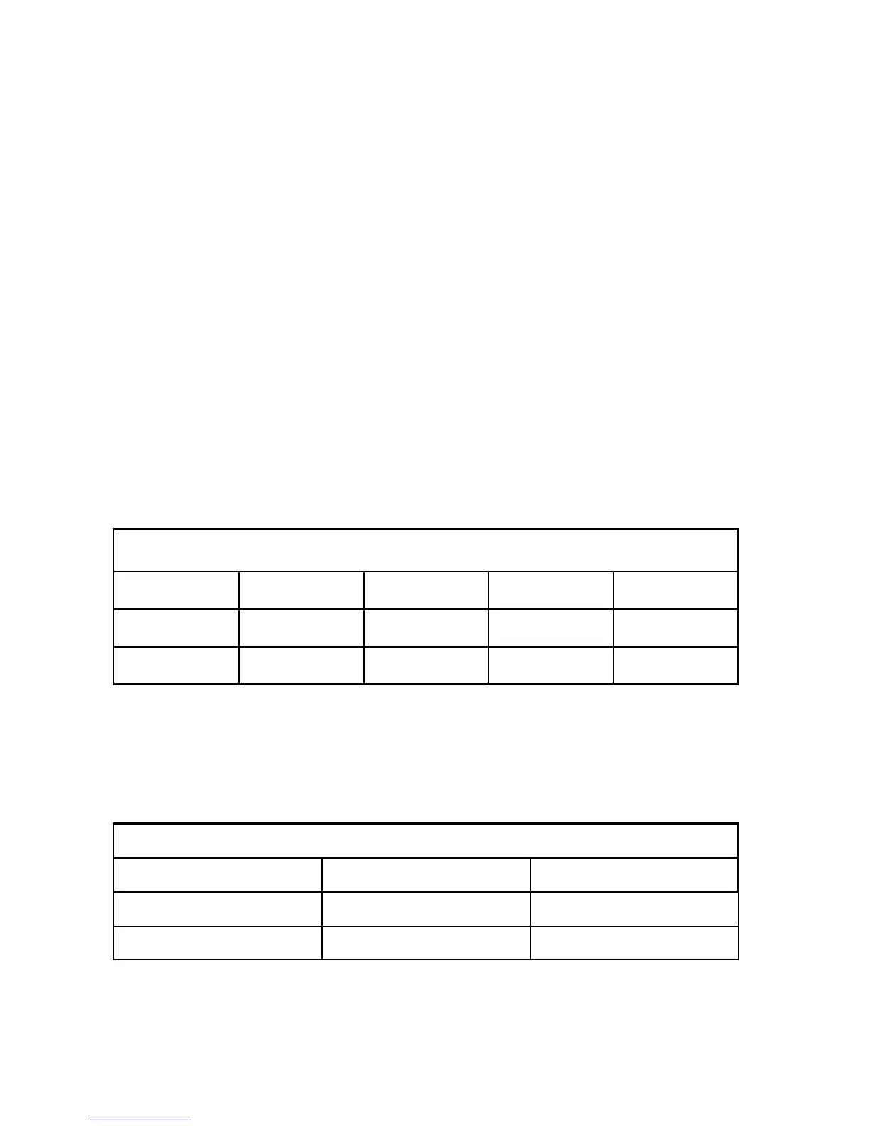
AUTO CUT AUTO COAG 1 AUTO COAG 2 AUTO BIPOLAR
Ab 2 nUI before activation
U NTG I NTG I NTG V1 nUI during activation
• U NTG Power supply voltage [V]; Set value = 223 V
• I NTG Power supply current [mA]; Set value = 447 mA
• I NTG V1 Amplified power supply current [mA]
• nUI Adjustment of the current voltage setting of the power supply generator
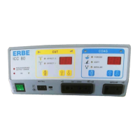
ICC 200
AUTO CUT AUTO COAG
nUI before activation
U NTG I NTG after activation
• U NTG Power supply voltage [V]; Set value = 223 V
• I NTG Power supply current [mA]; Set value = 447 mA



 To Next Page