1 TEST PROGRAMS AND ADJUSTMENTS98 / 266
Adjustment 12
Pulse/pause length ST output stage
Procedure
• Call up Test program 16, Adjustment 12.
• Measure actuation impulse TSI_STE at measuring point MP 3 on ST output stage (slot J6) with the
oscilloscope (measuring point MP1 = GND).
• Using TP16, set this to a pulse length of 200 ns (±50 ns).
IMPORTANT! The pulse time is measured at average amplitude, i.e. at approx. 7.5 volts level.
ATTENTION! The pulse is inverted.
• The repetition frequency at TP17 is set in such a way that the value 0 (tolerance 0...4) is displayed in
the AUTO CUT field.
• Now exit the test program and return the ICC to normal operating condition.
• To check the performance, connect the HF output to the HF power meter, setting 500 ohms.
• Activate the ICC using the blue footswitch pedal at the SPRAY and FORCED normal settings. The
power output in watts should correspond to the display in the AUTO COAG 2 field.
• Check whether the maximum emitted output power with SPRAY and FORCED is within the tolerance
limits (120 W ± 15 %). If necessary, conform the pulse length to the PCB control board using TP16.
TP17 must no longer be changed.
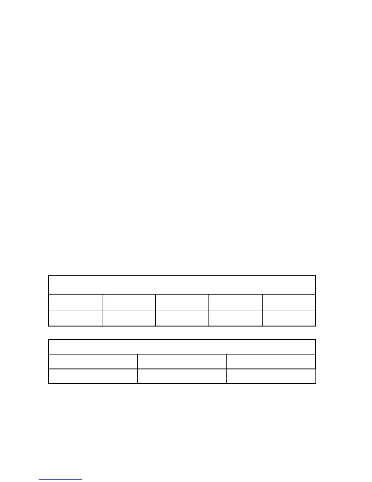
ICC 350
ICC 300
AUTO CUT AUTO COAG 1 AUTO COAG 2 AUTO BIPOLAR
xxx ppp tSt Standby
ICC 200
AUTO CUT AUTO COAG
xxx tSt Standby
• ppp Set AUTO COAG 2 FORCED power
• xxx Difference = Set frequency minus actual frequency