1 TEST PROGRAMS AND ADJUSTMENTS74 / 266
Procedure
• Call up Test program 16, Adjustment 6.
• With the same setup as for Adjustment 5, the unit is activated. At the same time, 5 watts (tolerance
4.5…5.5 watts) should be output at the HF power meter.
• Using TP 5 on the control board (slot J 3), the amplified HF voltage measurement is set in such a way
that a value of 50 volts HF output voltage is displayed in the AUTO CUT field.
• Using TP 6 on the control board, the amplified HF current measurement is set. The value 100 mA Hf
output current is displayed in the AUTO COAG 1 field when set correctly.
• In the Auto Bipolar field, the emitted active power is displayed.
• In the Auto Coag 2 field, the phase angle cos j is displayed.
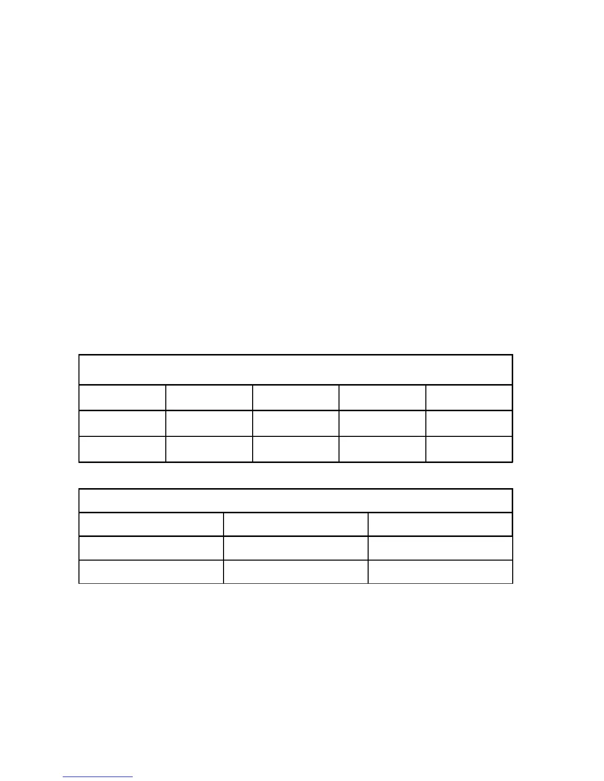
ICC 350
ICC 300
AUTO CUT AUTO COAG 1 AUTO COAG 2 AUTO BIPOLAR
Ab 6 UI before activation
U HF I HF cos Phi P during activation
ICC 200
AUTO CUT AUTO COAG
UI before activation
U HF I HF after activation
• U HF HF voltage amplified [V]; Set value = 50 V
• I HF Real part of the amplified HF current [mA]; Set value = 100 mA
• cos Phi Phase angle 0…100 from the table Set value = 100
• P Emitted active power [W]; Set value = 5 watts at 500 R
ICC 200:
cos-j display appears when the “Up” (8) key is pressed.
P-display appears when the “Down” (9) key is pressed.
Adjustment 6
HF generator output parameters amplified