1 TEST PROGRAMS AND ADJUSTMENTS78 / 266
Adjustment 7
Phase angle (cos j)
Procedure
• Call up Test program 16, Adjustment 7.
• Using ERBE original cable, connect the APM 600 (set at 500 ohms) to the ICC; with 2 monopolar
connections: Connect active output socket: CUT / COAG 2 (ICC 300 / 350) and NE socket.
• Connect a capacitor with 1 nF (e.g. ERBE component no. EE 51103-026) with short lines across the
active electrode and NE sockets on the HF power meter.
This produces a phase shift between voltage and current of 45° at a frequency of 340 kHz.
• Activate the cut footswitch.
• Using TP 7 on the control board (slot J3), the unit is set in such a way a value of 73 (display is
100 · cos j) is displayed in the AUTO CUT field and a value of 120 (analog / digital converter
measured value) is displayed in the AUTO COAG 1 field.
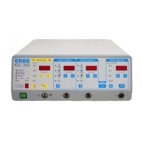
ICC 350
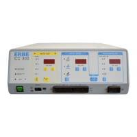
ICC 300
AUTO CUT AUTO COAG 1 AUTO COAG 2 AUTO BIPOLAR
Ab 7 PHI before activation
COS xxx PHI during activation
ICC 200
AUTO CUT AUTO COAG
PHI before activation
COS xxx after activation
• COS cos-j values from table; Set value = 73
0 means phase shifting = 90°
100 means phase shifting = 0°
• xxx Analog cos-j measurement value; Range 0…255
• V
eff
HF output voltage;
200 mA output current limitation



 To Next Page