1 TEST PROGRAMS AND ADJUSTMENTS86 / 266
Adjustment 9
NESSY resistance measurement
Procedure
• Call up Test program 16, Adjustment 9.
• Connect an NE cable to the NE input receptacle on the ICC system.
• Connect the other end of the NE cable between 120 ohms of resistance.
• Set TP9 on the control board (slot J3) in such a way that a measurement value of 200 for the A/D
converter is displayed in the AUTO CUT field and a resistance of 120 ohms is displayed in the AUTO
COAG 1 field.
• Now exchange the terminating resistor for a resistance value of 40 ohms. Now verify the measurement
at this resistance; a resistance of 40 ohms (tolerance 37...43 ohms) must be displayed in the AUTO
COAG 1 field.
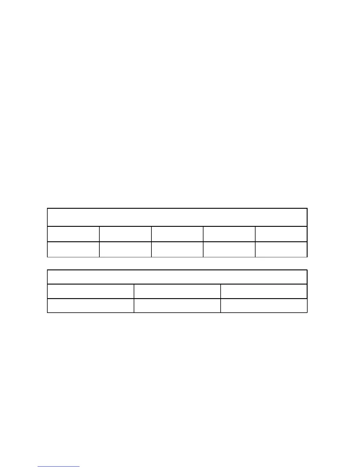
ICC 350
ICC 300
AUTO CUT AUTO COAG 1 AUTO COAG 2 AUTO BIPOLAR
xxx R üb r Standby
ICC 200
AUTO CUT AUTO COAG
xxx R üb Standby
• R üb Contact resistance at the neutral electrode [W]
• xxx Analog measurement value of the contact resistance.
For resistance values outside the measurement accurary, the display --- appears.