1 TEST PROGRAMS AND ADJUSTMENTS90 / 266
Adjustment 10
HF leakage current measurement
Procedure (This adjustment only applies to the ICC 350)
• Call up Test program 16, Adjustment 10.
• Connect the HF power meter (set to 350 ohms load resistance) between the active electrode of the
CUT / COAG 2 (center) socket and the potential equalization.
• Jumper J3 must be plugged into the display board for this adjustment (earthed reference).
• Short together the NE-ERBE original adapter cable. Activate the ICC 350 using the blue footswitch
pedal (AUTO COAG 1).
• Using the power setting in the AUTO COAG 1 field, set the leakage current flowing to ground to a
value of 150 mA
eff
(tolerance 131…169 mA) (use an HF effective current meter or set a power of 7.9
watts at a HF power meter with a load resistance of 350 ohms [tolerance 6.0…10 watts (from P = I² · R
with P = 7.9 watts and R = 350 ohms is a current I = 150 mA)]).
• Set TP10 on the control board (slot J3) in such a way that the HF leakage alarm is thus displayed
visually (the LED in the safety field flashes in the display indicates the value 50 in the Auto Cut
field).
• Increase the leakage current by changing the power setting until an audible alarm is also emitted.
This should occur at 300…350 mA (accordingly 31.5…43 watts on a HF power meter at the above
setting).
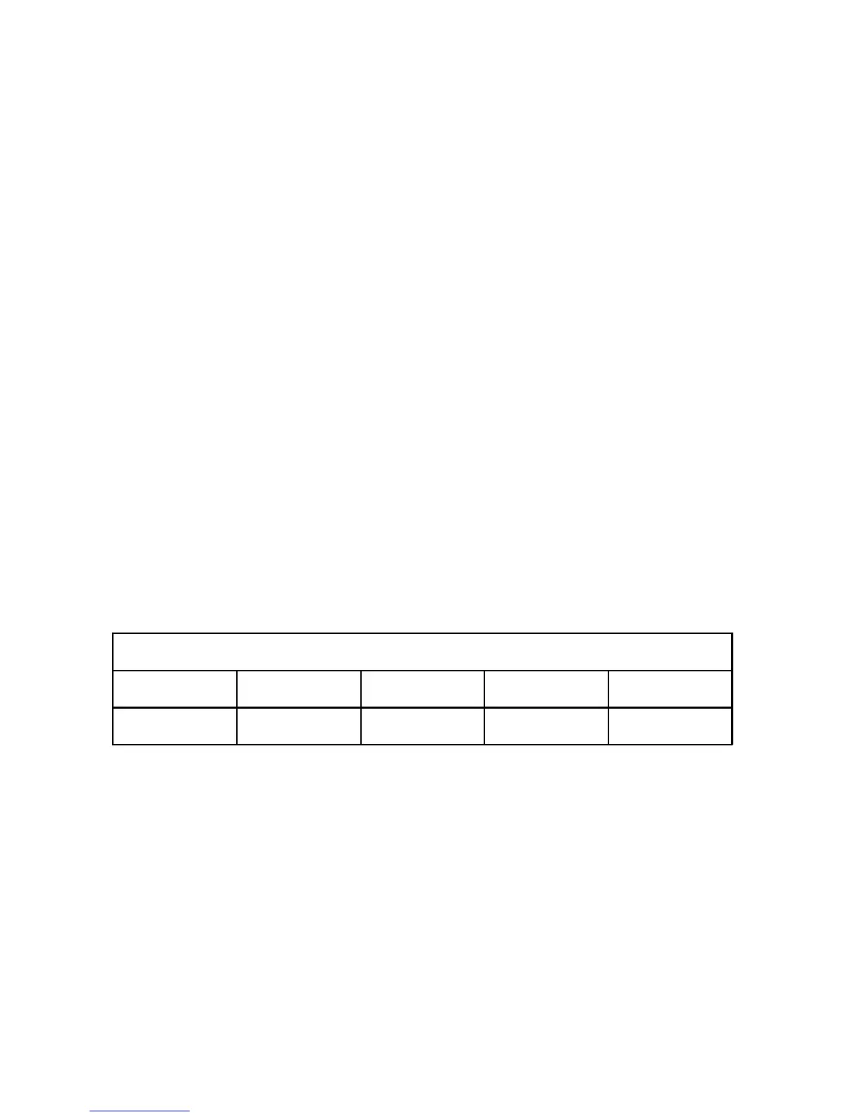
ICC 350
AUTO CUT AUTO COAG 1 AUTO COAG 2 AUTO BIPOLAR
xxx ppp HFL Standby
• ppp Set SOFT COAG power which can be changed during activation.
• xxx Measurement value of the HF leakage current measurement.
Using the power setting in the AUTO COAG 1 field, set the HF leakage current flowing to ground at
I
eff
= 150 mA. This is not assigned for the ICC 200 and 300 since no HF leakage current monitor is
available there.