1 TEST PROGRAMS AND ADJUSTMENTS70 / 266
Adjustment 5
HF generator output parameters
Procedure
• Call up Test program 16, Adjustment 5.
• Connect the HF power meter, e.g. APM 600 (set to 500 ohms) via active cable to active and neutral
electrode output sockets on the ICC; for 2 monopolar outputs: CUT / COAG 2 output and NE socket.
• Activate the unit with the yellow pedal of the footswitch (AUTO CUT).
• Using TP3 on the control board (slot J3), the HF output voltage is set in such a way that a power of
100 watts is indicated on the HF power meter and a value of 223 volts HF effective voltage (tolerance
220…223 volts) in the display on the AUTO CUT field.
• Under certain conditions, TP 4 (HF current limitation) must be turned back far enough before this
setting so that no current limitation is effective.
• Using TP4 on the control board (slot J3), the HF current limitation is set in such a way that a value of
447 mA effective HF current (tolerance 439…447 mA) with constant power output appears in the
AUTO COAG 1 field.
• Insofar as the measurement of the phase angle between HF voltage and HF current produces a value
greater than 98 (which is 100 · cos j) at this setting in the AUTO COAG 2 field, a value of 100 watts
HF power output is displayed (tolerance 97...100 watts) in the AUTO BIPOLAR field after correct
adjustment of voltage and current.
• For the voltage characteristic at a 500 ohms load, see Fig.
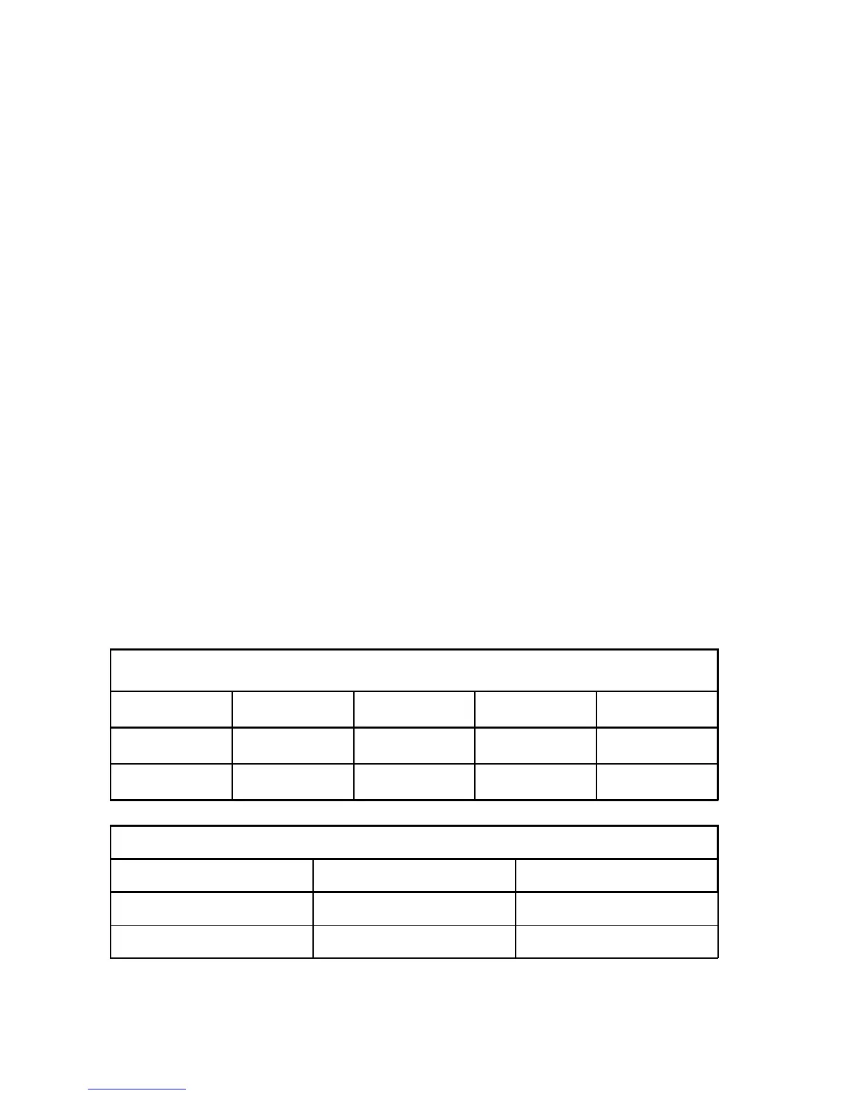
ICC 350
ICC 300
AUTO CUT AUTO COAG 1 AUTO COAG 2 AUTO BIPOLAR
Ab 5 UI before activation
U HF I HF cos Phi P during activation
ICC 200
AUTO CUT AUTO COAG
UI before activation
U HF I HF after activation
• U HF HF voltage [V]; Set value = 223 V
• I HF Real part of HF current [mA]; Set value = 447 mA