1 TEST PROGRAMS AND ADJUSTMENTS82 / 266
Adjustment 8
Spark monitor
Procedure (also applies to the units without HIGH CUT or ENDO CUT)
• On the ICC 300 and ICC 200 without ENDOCUT, TP8 should be set to the upper limit (to do this,
turn TP8 clockwise).
• Call up Test program 16, Adjustment 8.
• A DC voltage of 70 volts is fed into the patient circuit between the center control for the active AE
socket (with 2 monopolar outputs: Output CUT / COAG 2) and the neutral electrode NE socket (AE =
+, NE = –). To do this, the ERBE TESTBOX 70 volts is recommended (ERBE Order no. 20100-019).
• Adjust TP8 on the control board (slot J3) is set in such a way that a measurement value of 77 is
indicated for the A/D converter, and a value of 70 volts DC is displayed in the AUTO COAG 1 field.
On the ICC 200 ENDOCUT, this value appears in the AUTO CUT field, while the A/D converter
value is not shown.
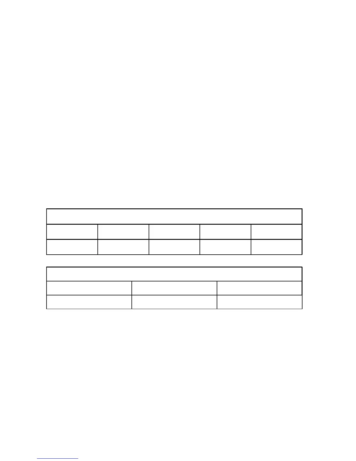
ICC 350
AUTO CUT AUTO COAG 1 AUTO COAG 2 AUTO BIPOLAR
xxx yyy FU Standby
ICC 200 ENDO CUT
AUTO CUT AUTO COAG
yyy FU Standby
• yyy Fed-in DC voltage for the spark measurement value (70 V)
• xxx Analog spark measurement value
The input for applying the test DC voltage is the CUT / COAG 2 socket.