MINI-LINK BAS 3-12
Technical Description EN/LZB 111 0542 P2B
PBX
AT
AT
AT
AT
Radio
Shelf
AT
AT
AT
AT
RN
RN
ATM
Radio
Shelf
HUB 1
HUB 2
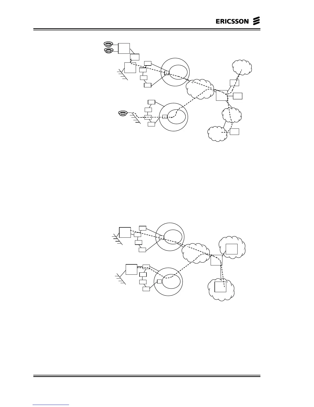
R = Router
G/W = H. 323 Gateway
AT = Access Termination
RN = Radio Node
GK = Gatekeeper
G/W
R
LAN
LAN
R
G/W
G/K
G/W
INTERNET
PSTN
PSTN
H. 323 Terminal
Figure 3-9 System Deployed for IP Telephony (PBX-PSTN, PBX-
H.323 terminal)
Subscriber’s datacom traffic is bridged at Ethernet interface to provide
a demarcation point between the CPE LAN and the public network.
Typically a router can provide the operator with many options for
multiple ISP access, billing and security for Internet and Intranet
solutions.
AT
AT
AT
AT
Radio
Shelf
AT
AT
AT
AT
RN
RN
ATM
Radio
Shelf
HUB 1
HUB 2
R = Router
AT = Access Termination
RN = Radio Node
R
LAN
LAN
R2
R
R3
ISP 1
R3
ISP 2
Figure 3-10 System Deployed for Data Traffic and Multiple IP
Selection