53
6.5 Reference Voltage Checks
A. Control Board Assembly (PCB1)
1. Voltage Test Points - Tests are made with power on - no arc.
TP-15 - Ground
TP-12 - +15 vdc
TP-13 - +5 vdc
TP-14 - -15 vdc
B. Interface Board (PCB2)
1. Voltage Test Points 2. LED's
TP-1 - +24 vdc D18 - Torch Trigger
TP-2 - +24 vdc com
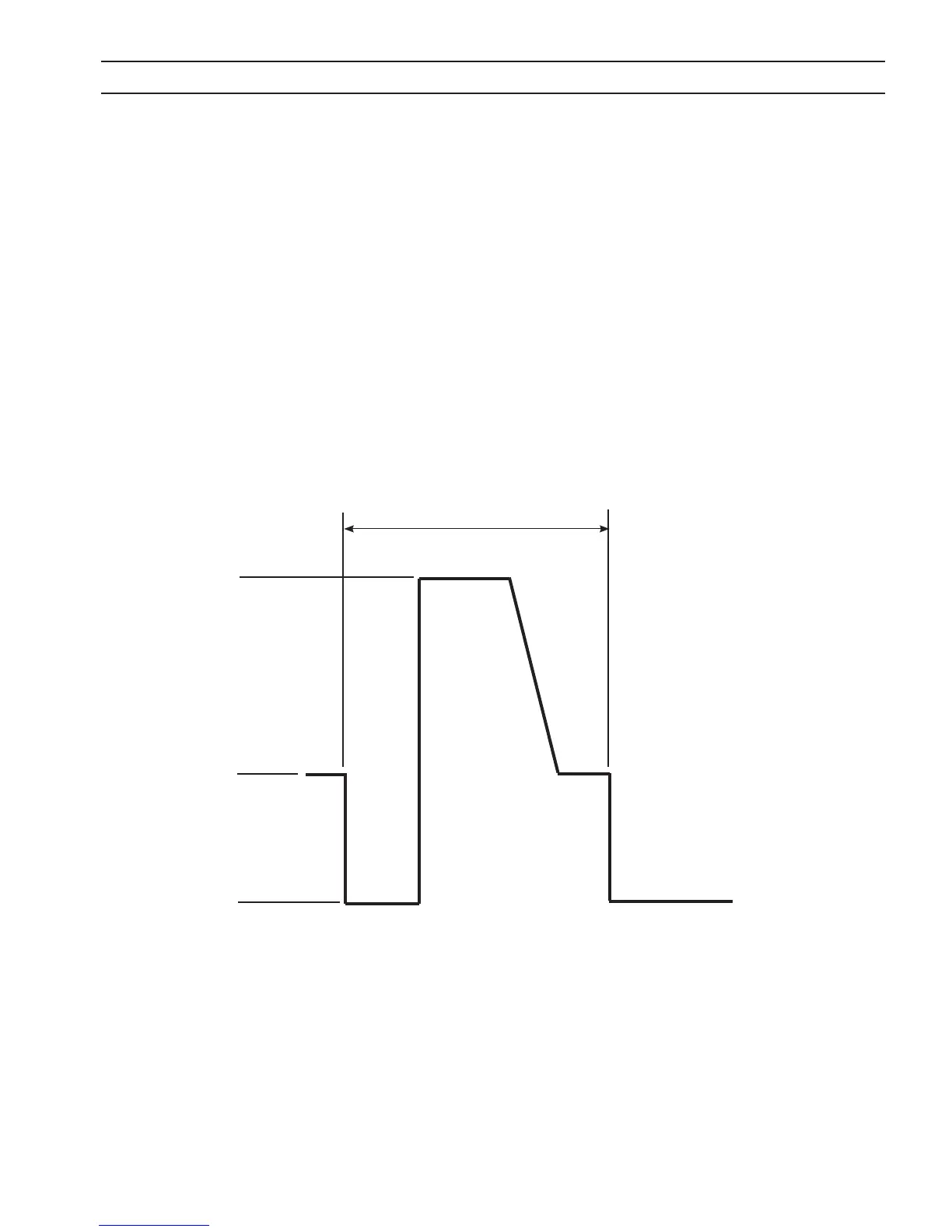
For 208/230 VAC input, the IGBT o time is 3µsec.
For 400/460 VAC input, the IGBT o time is 3µsec.
Figure 6.1 IGBT Gating Signal
SECTION 6 TROUBLESHOOTING
15 vdc
0
54 µsec
36 vdc