29
SECTION 3 INSTALLATION
MAKE SURE POWER SWITCH ON CONSOLE IS IN OFF POSITION AND
PRIMARY INPUT POWER IS DEENERGIZED.
3.7 Voltage Divider Adjustment
It may be necessary to adjust the Voltage Divider or VDR to match the particular height control system. There are two de-
fault settings for the ESP-101 models as shipped from the factory:
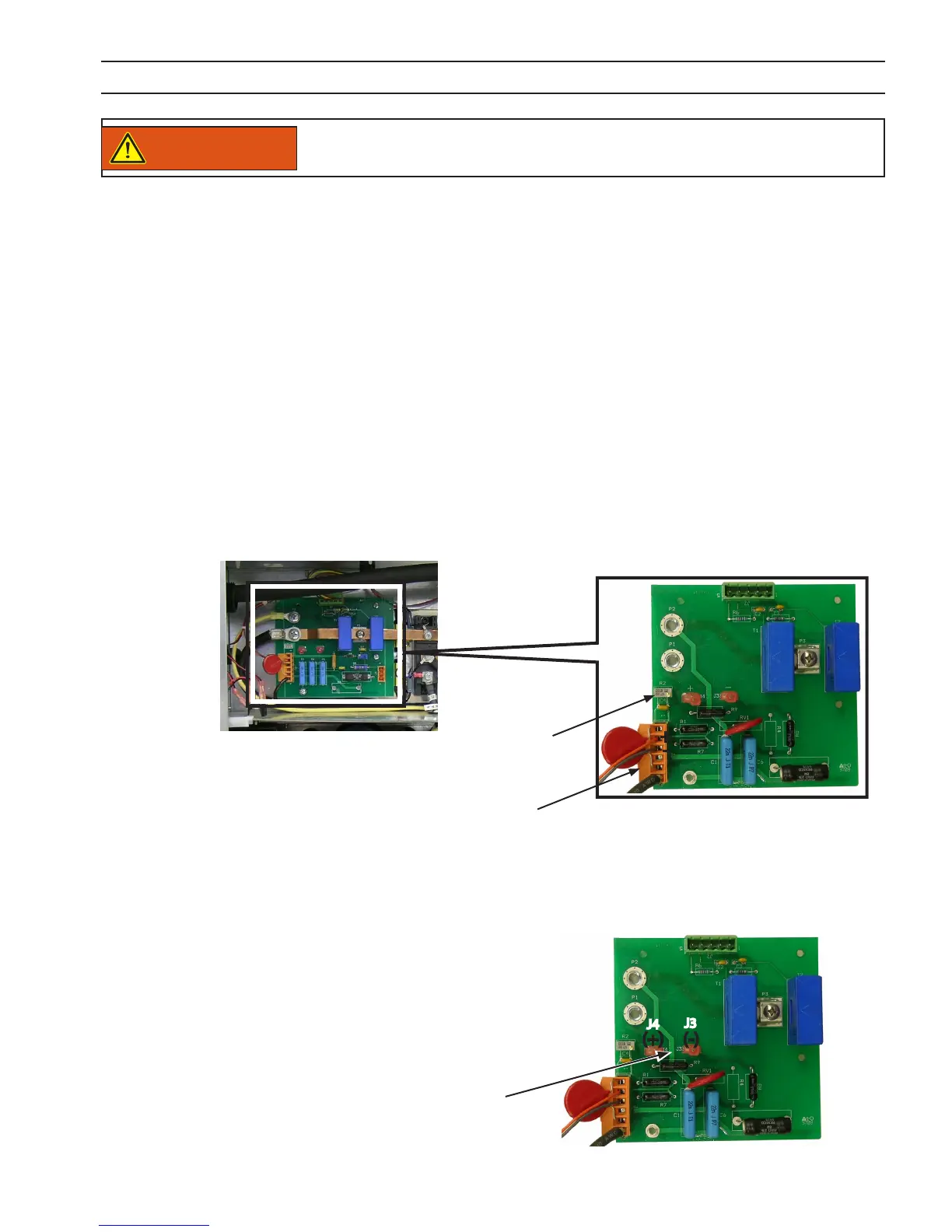
1. Place ohm meter leads between P1-2 (orn) & P1-3 (gry). Adjust R2 to achieve the desired divide ratio for the
particular height control system used. For example:
Potentiometer
(R2)
• STANDARD UNITS (Non-CE): 750 ohms (21:1)
• 16:1 ratio 1000 ohms
• 18:1 ratio 882 ohms
• 21:1 ratio 750 ohms
• 20:1 ratio 789 ohms
2. If desired, additional minor adjustments of the VDR potentiometer may be made. Any adjustments should be
performed by a qualied technician.
• CE UNITS (Europe): 789 ohms (20:1)
If the height control system does not match the factory default setting, matching can be accomplished by adjusting the
VDR potentiometer on the Current Sensor PCB4 located behind the left side panel.
3.7.1 Output Voltage Sample
1. Remove insulated terminals to provide access to the male
spade terminals. (If needed, the insulated terminals may
then be used to terminate the voltage pickup wires.)
Output Voltage Sample - Some Cutting Machines sample the full output voltage of the plasma system to control the torch
height and to determine when to start moving. The full output voltage is available within the machine on a pair of male
spade terminals (J3 and J4).
Output Voltage Sample
Note:
Ohm meter readings can also be taken at the CNC receptacle on the rear panel of the machine, between pins C and H.
+
-
P1
(+) (-)
J3
J4
WARNING