24
3.5.1 TUA2 Auto-Transformer Primary Input Connections
SECTION 3 INSTALLATION
Connecting a Multi-Voltage Version
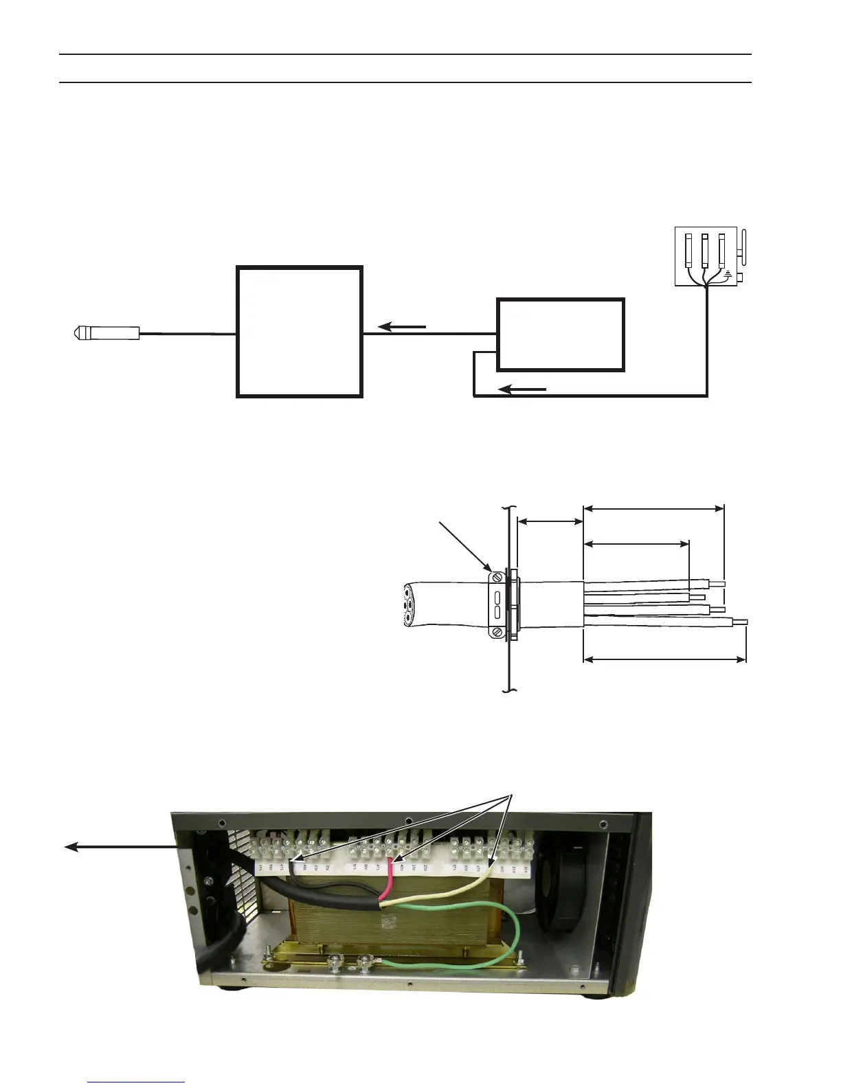
The ESP-101 460V version is equipped with an input power cable which may be used to connect to the output of the TUA2
Auto-Transformer. You may either use the factory-installed input power cable (4/c, type SO (90 °C) or provide your own in-
put power leads. If you choose to provide your own, make sure they are insulated copper conductors. You must have three
(3 phase) power leads and one ground wire. Refer to Table 3-1 for recommended input conductors.
Figure 3-2b. Primary Power Cable from ESP-101 to TUA2 Auto-Transformer
Step 2: Route the power cable through the upper strain relief of the TUA2 Auto-Transformer as shown below. Connect L1,
L2, L3 leads to the 460 V terminals. Connect the ground lead to the forward ground stud. Ensure all connections
are secure. Do not overtighten the strain relief.
10"
(254 mm)
7"
(178 mm)
3"
(76 mm)
16"
(406 mm)
Note:
L1, L2 & L3 strip wires 3/8" (9.5 mm) .
GND wire strip 1" (25.4 mm) or
5/16" ring terminal.
L1
L2
L3
GND
Upper Strain Relief
460 V Terminals
To ESP-101 460 V
console
Primary Power Cable from ESP-101 to TUA2 Auto-Transformer
Step 1: Begin by preparing the power cable,
then positioning in the TUA2 as shown.
Figure 3-2c. Primary Power Cable from ESP-101 to TUA2 Auto-Transformer 460 V Terminals
Figure 3-2a. Connection Diagram for TUA2 Auto-Transformer
from 460 V
terminals
3-phase w/
ground
ESP-101
460V
Console
TUA2
Auto-
Transformer
PT-37 Torch
4.5’, 17', 25', 50’
to appropriate supply
voltage terminals