25
SECTION 3 INSTALLATION
The TUA2 Auto-Transformer is not equipped with an input power cable. A 4/c, type SO (90 °C) cable or equivalent is recom-
mended. Ensure they are insulated copper conductors. You must have three (3 phase) power leads and one ground wire.
Select an input power cable size corresponding to the input supply voltage listed in Table 3.1.
Primary Power Cable from Fused Line Disconnect Switch
to TUA2 Auto-Transformer
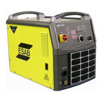
Figure 3-3a. Primary Power Cable from Fused Line Disconnect Switch
to TUA2 Auto-Transformer
Note:
L1, L2 & L3 strip wires 3/8" (9.5 mm) .
GND wire strip 1" (25.4 mm) or
5/16" ring terminal.
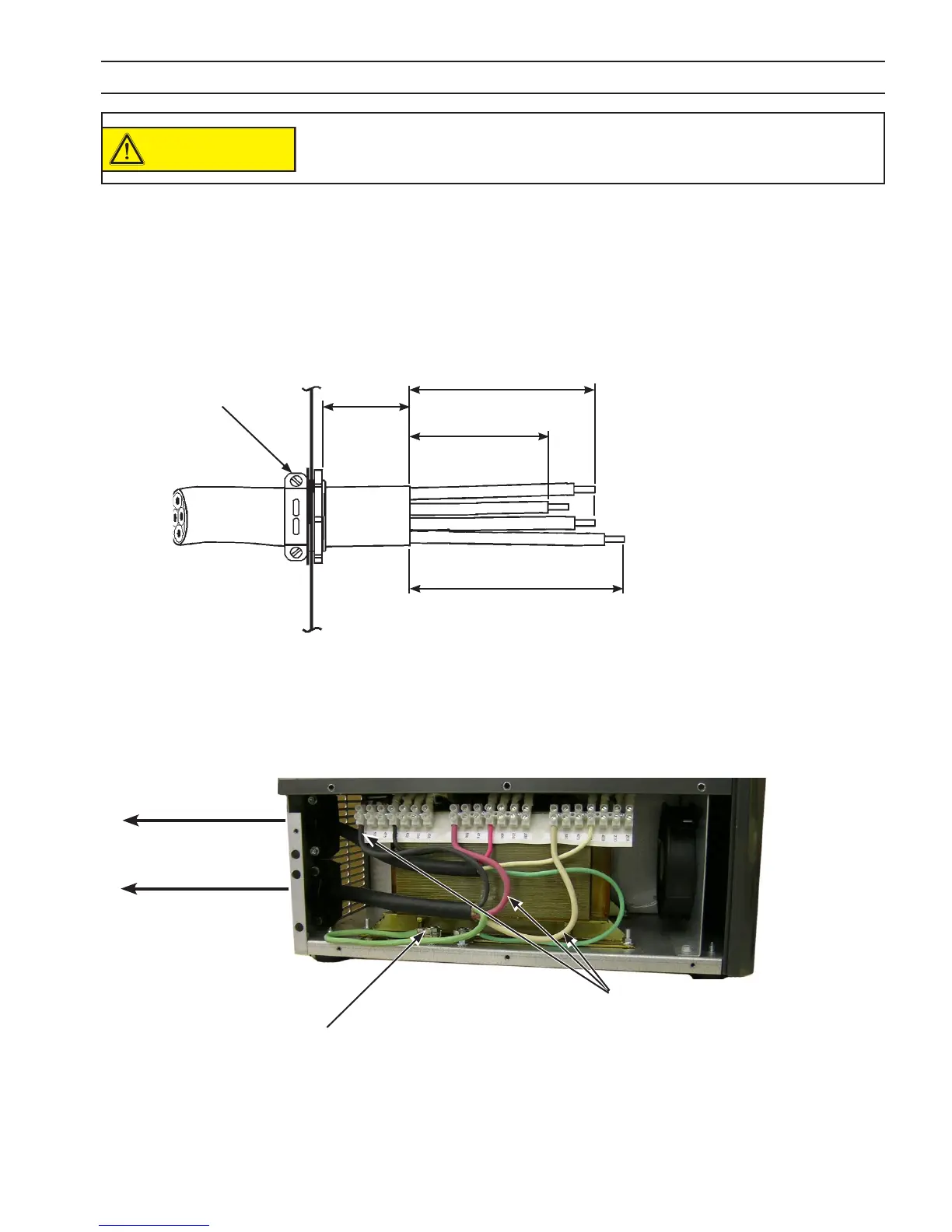
Step 2: Route the power cable through the lower strain relief of the TUA2 Auto-Transformer as shown below. Connect L1,
L2, L3 leads to the voltage terminals that match your input power supply voltage. Connect the ground lead to the
rear ground stud. Ensure all connections are secure. Do not overtighten the strain relief.
Lower Strain Relief
Step 1: Begin by preparing the power cable, then positioning in the TUA2 as shown:
10"
(254 mm)
10 1/2"
(266.7 mm)
8"
(203.2 mm)
18"
(457.2 mm)
L1
L2
L3
GND
Ensure three input power jumper cables are connected properly to the
Auto-Transformer for your input power.
Appropriate supply
voltage terminals
Ground Connection
Figure 3-3b. Primary Power Cable from Fused Line Disconnect Switch
to TUA2 Auto-Transformer appropriate supply voltage terminals
(575 V pictured)
To Fused Line
Disconnect Switch
To ESP-101 460 V
console
CAUTION