Fire Alarm Computer 8000C
Page 77
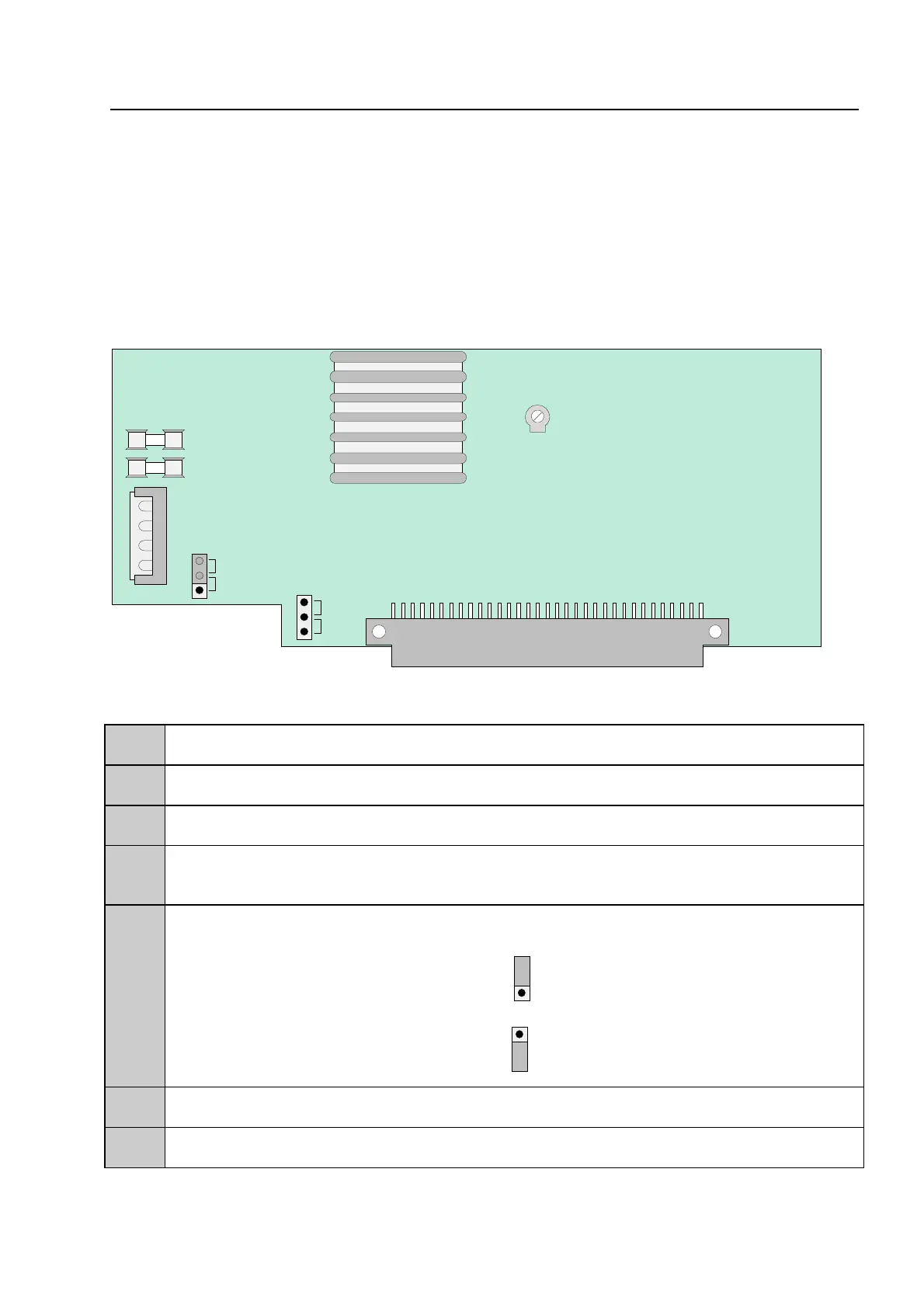
10.5 Power supply module
The power supply module is installed on the basic circuit board of the FACP 8000C. This module
accommodates the entire voltage supply for the fire alarm control panel and the +12 V DC supply
voltage for external devices.
Maximum current load from external users will depend on control panel configuration and accounts
for approx. 2A. One power supply module may be installed in each FACP 8000C. If necessary,
additional supply is possible from a monitored external power supply unit.
Fig. 35: Power supply module
X1
Contact for transformer connection (secondary side)
F1
Fuse for internal control panel supply voltage to the analog ring loop +27.5 V DC/ T1.6A
F2
Fuse for secondary side MT6.3A
BR1
Activation/deactivation of automatic ground-fault detection
(factory setting = ON)
BR2
Deep discharging of the batteries
Deep discharging protection enabled
ON
1
2
3
(factory setting)
Deep discharging protection disabled
OFF
1
2
3
R15
Potentiometer for adjusting the battery charge voltage to +13.9 V DC (at 25°C)
X 5/6
Plug strip to basic card (terminal X15/X16)
Power supply module
1
2
3
4
1
2
3
BR1
F1
Power supply module
F2
R15
X1
1
2
3
ON
OFF
BR2
ON
OFF
X5/6