Page 82
Fire Alarm Computer 8000C
The basic module accommodates the microprocessor for controlling the control panel functions,
the operating system EPROM and the customer data EEPROM for storing the data entered in
customer data programming.
The basic module holds the power supply module for supplying voltage to the control panel and
interfaced external devices. The basic module is also able to accommodate a freely selectable
micromodule. A Field device module or a extension module is fitted to slots Plug 1.
Peripheral modules or extension modules may only be installed in
slot 1
of the basic
module.
Slot 2
of the basic module is inoperative on the 8000C FACP. No modules may
inserted into
slot 2
.
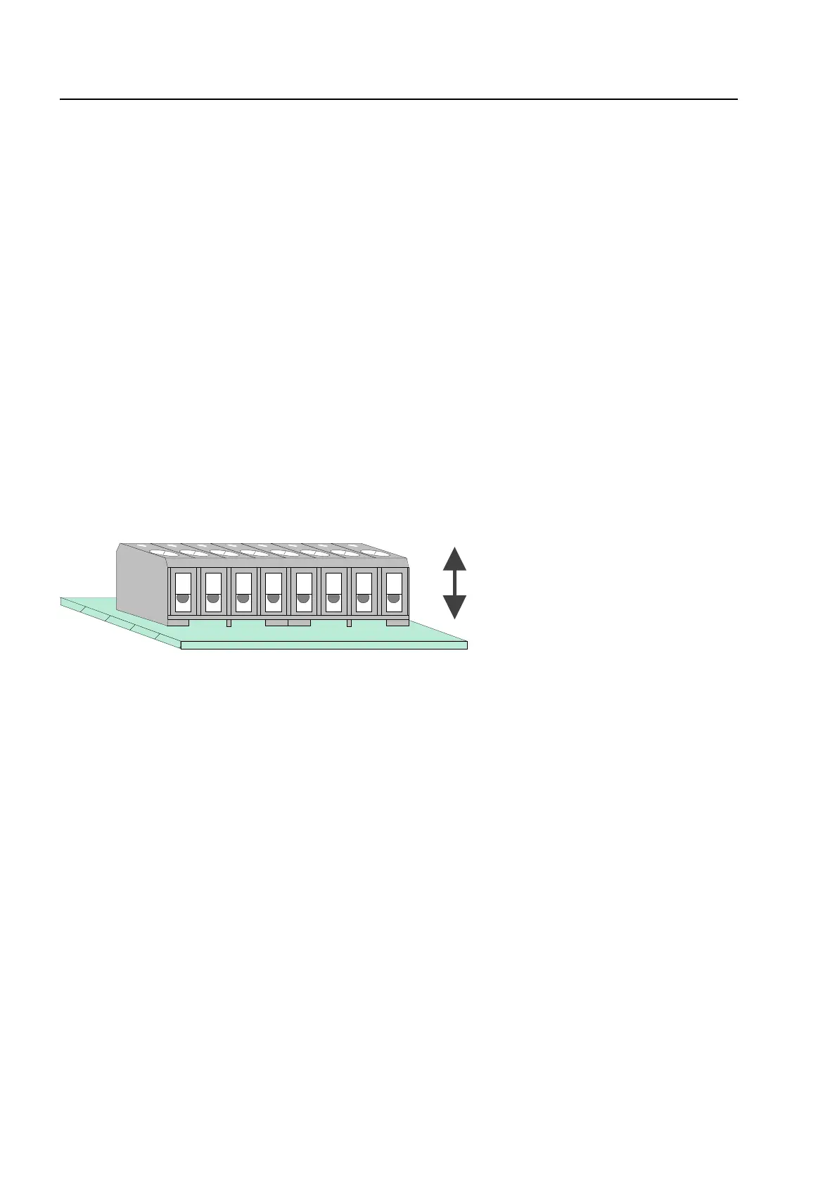
Connection terminals
To simplify installation, you may detach the connection terminals from the basic card. After
connecting the wires, fit the terminal strip back onto the plug-in contacts on the basic card.
Fig. 38: Connection terminals
10.6.1 Mains connection
Connection of the 230 V AC mains supply lead for voltage supply to the fire alarm control panel.
♦
A separate power circuit with appropriately marked fuse (market red, labeled "FACP") must be
used for supplying the fire alarm control panel with mains power.
♦
Use an appropriate mains cable, e.g. NYM 3 x 1.5 mm
2
or a cable type with similar
specifications.
♦
The 230 V AC connection must be carried out by a qualified technician in accordance with
current regulations.
Basic module
removable