Page 84
Fire Alarm Computer 8000C
10.6.2 Connecting the micromodule
Eight connection terminals are provided at slot X17/18 on the basic card for connecting the freely
selectable micromodule. Assignment of the eight screw terminals will depend on the micromodule
type used. Terminal card assignment is described for each micromodule in Section
Micromodule
.
All jumpers in vertical position
X11 X12 X13
X14
⇒
EMC protection for this micromodule connection
terminal is activated (state on leaving the factory)
All jumpers in horizontal position
X11 X12 X13
X14
⇒
Only required for essernet
®
micromodule type 2
(500 Kbit/s). EMC protection for this micromodule
connection terminal is out of operation.
If a essernet
®
micro module (500 Kbit/s) is used in the micro module slot, the integrated
EMC filter must be disabled. EMC protection of the essernet
®
cabling has to be ensured
by appropriate external devices.
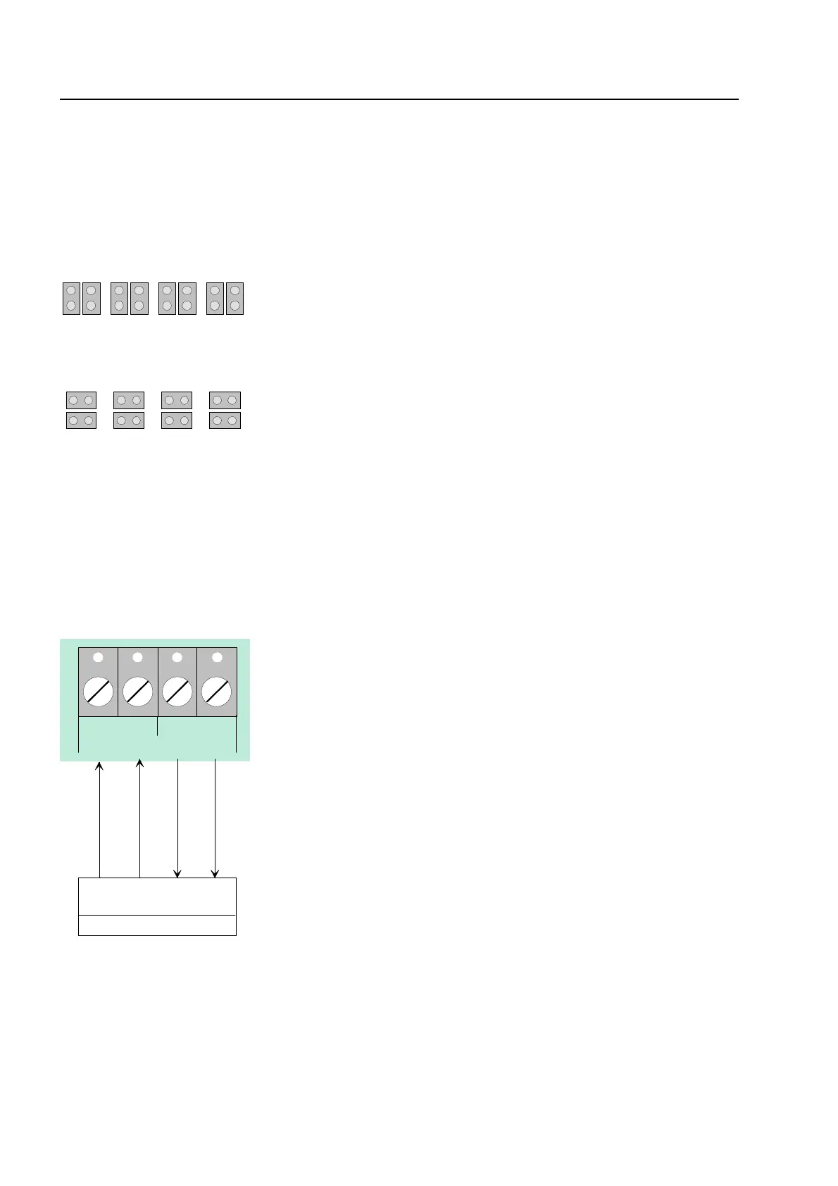
10.6.3 Serial interface
AB A
RxD TxD
B
external device
Rx -Rx +Tx -Tx +
send
receive
TTY
receive
send
These four terminals may be used for connecting an
external device, e.g. a protocol printer, via the TTY
interface (20 mA).
The line length between external device and interface
must not exceed 1000m.
If wired correctly, the green LED V56 will blink at the
transmission frequency to provide visual indication of
proper interface wiring.
If the connection cables are transposed at the
terminals, red LED V 44 will light up.
The connection terminals A/B of the RS485 interface on the basic module are reserved for future
function extensions and are not supported on this version of the central unit.
Basic module