ECM-3610/3610L
ECM-3610/3610L User’s Manual 25
3.7.9 Signal Description – Serial Port 1 – COM1 in RS-232 Mode (CM2)
TxD Serial output. This signal sends serial data to the communication link. The signal is set to a
marking state on hardware reset when the transmitter is empty or when loop mode operation
is initiated.
RxD Serial input. This signal receives serial data from the communication link.
DTR Data Terminal Ready. This signal indicates to the modem or data set that the on-board
is ready to establish a communication link.
DSR Data Set Ready. This signal indicates that the modem or data set is ready to establish a
communication link.
RTS Request To Send. This signal indicates to the modem or data set that the on-board UART is
ready to exchange data.
CTS Clear To Send. This signal indicates that the modem or data set is ready to exchange data.
DCD Data Carrier Detect. This signal indicates that the modem or data set has detected the data
carrier.
RI Ring Indicator. This signal indicates that the modem has received a telephone ringing signal.
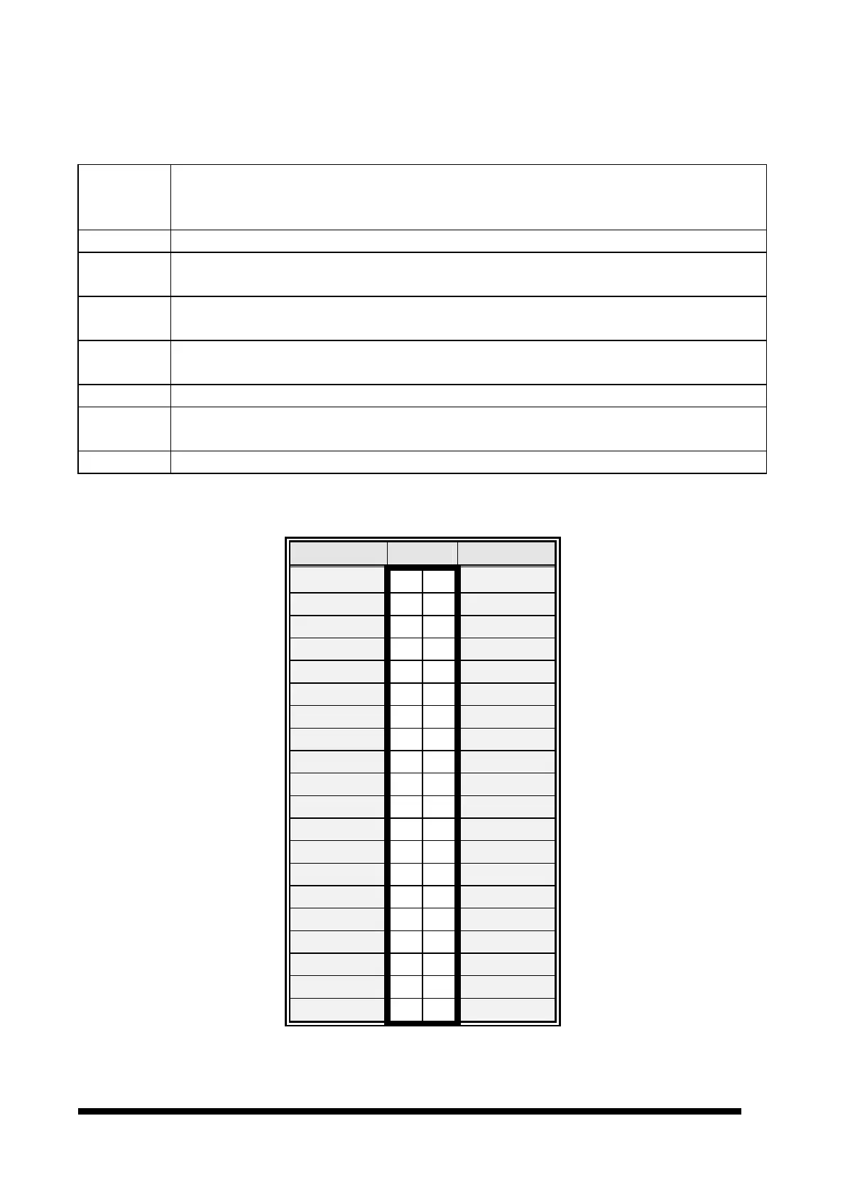
3.7.10 Secondary LCD Panel Connector (CN1)
Signal PIN Signal
5V 2 1
5V
GND 4 3
GND
3.3V 6 5
3.3V
GND 8 7
Vcon
P25 10
9
P24
P27 12
11
P26
P29 14
13
P28
P31 16
15
P30
P33 18
17
P32
P35 20
19
P34
GND 22
21
GND
Y2M 24
23
Y2P
Z1M 26
25
Z1P
ZCM 28
27
ZCP
Z0M 30
29
Z0P
YCM 32
31
YCP
GND 34
33
GND
Y0M 36
35
Y0P
Z2M 38
37
Z2P
Y1M 40
39
Y1P