User’s Manual
26 ECM-3610/3610L User’s Manual
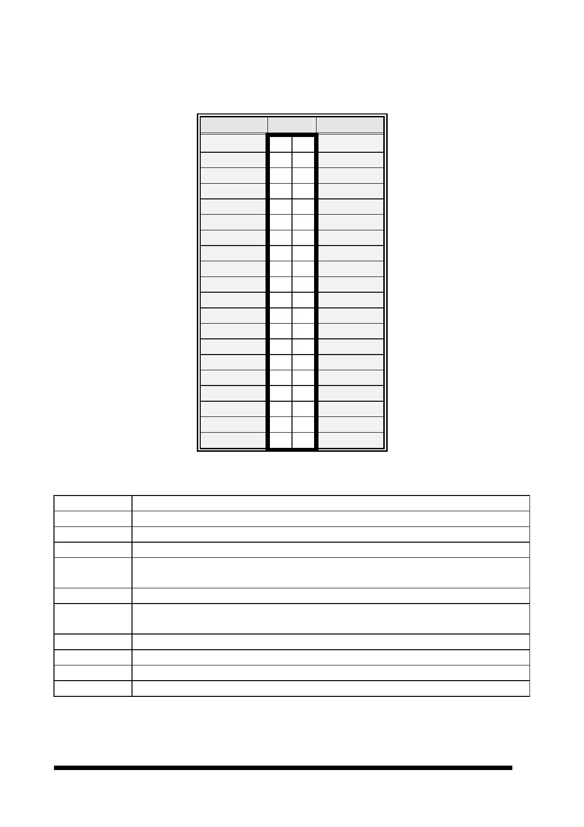
3.7.11 Primary LCD Panel Connector (CN2)
Signal PIN Signal
5V 2 1
5V
GND 4 3
GND
3.3V 6 5
3.3V
GND 8 7
Vcon
P1 10
9
P0
P3 12
11
P2
P5 14
13
P4
P7 16
15
P6
P9 18
17
P8
P11 20
19
P10
P13 22
21
P12
P15 24
23
P14
P17 26
25
P16
P19 28
27
P18
P21 30
29
P20
P23 32
31
P22
GND 34
33
GND
FLM 36
35
SHFCLK
LP 38
37
M
ENVEE 40
39
ENBKL
3.7.12 Signal Description – Primary & Secondary LCD Panel Connector (CN2, CN1)
P [35:0] Flat Panel Data Bit 35 to Bit 0 for panel implementation.
SHFCLK Shift Clock. Pixel clock for flat panel data
LP Latch Pulse. Flat panel equivalent of HSYNC (horizontal synchronization)
FLM First Line Marker. Flat panel equivalent of VSYNC (vertical synchronization)
M
Multipurpose signal, function depends on panel type. May be used as AC drive control
signal or as BLANK# or Display Enable signal
ENBKL Enable backlight signal. This signal is controlled as a part of the panel power sequencing
ENVEE
Enable VEE. Signal to control the panel power-
on/off sequencing. A high level may turn
on the VEE (LCD bias voltage) supply to the panel
Y[2:0]P, Z[2:0]P
1
st
& 2
nd
Channel Positive LVDS differentiaI data output
Y[2:0]M, Z[2:0]M
1
st
& 2
nd
Channel Negative LVDS differential data output
YCP, ZCP
1
st
& 2
nd
Channel Positive LVDS differential clock output
YCM, ZCM
1
st
& 2
nd
Channel Negative LVDS differential clock output