ECM-3610/3610L
ECM-3610/3610L User’s Manual 39
3.7.30 ATX Power Connector (J1)
Signal PIN
PS_ON#
1
VCC 2
VCC_SB
3
Note:
Set J1 to 2-3 closed. If AT power supply is to be used.
3.7.31 ATX Soft-power Bottom (J2)
Signal PIN
PWRBTN
1
GND 2
3.7.32 Signal Description – ATX Soft-power Bottom (J2)
PWBTN Power Button
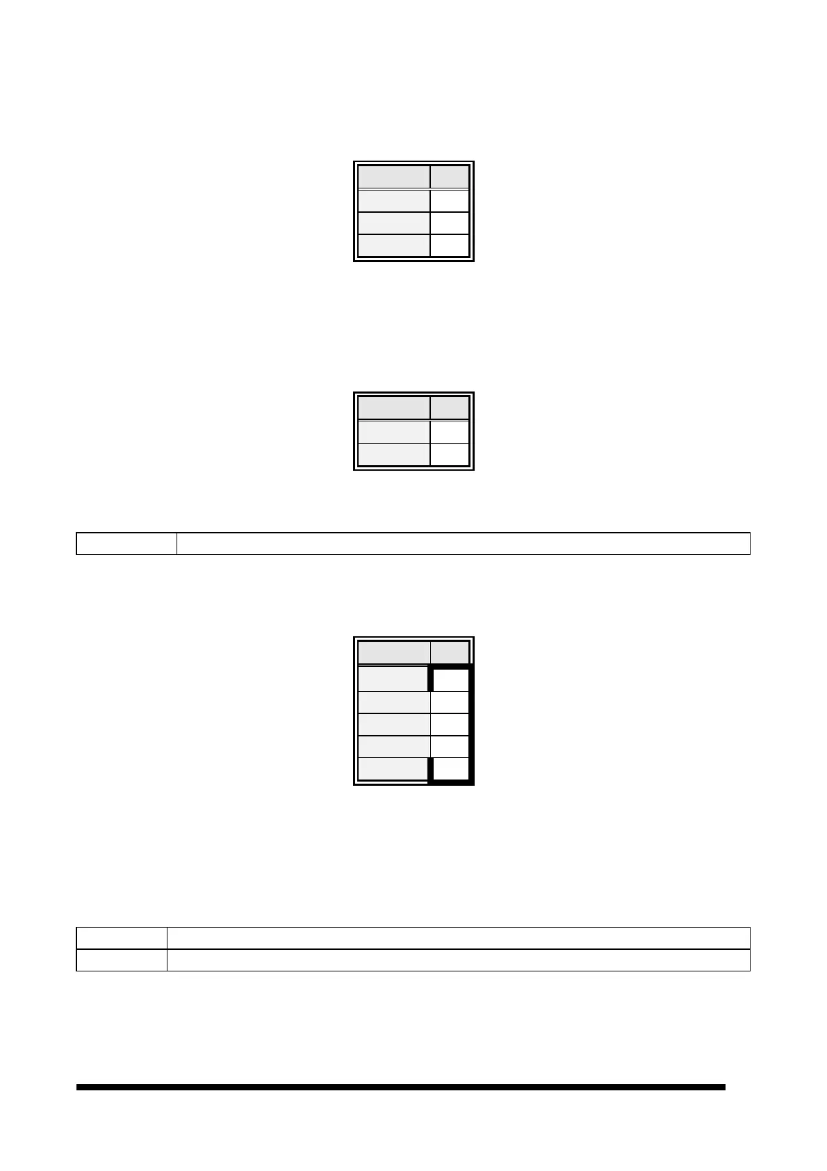
3.7.33 LCD Inverter Connector (J3)
Signal PIN
VCC 5
VR 4
ENBKL 3
GND 2
+12V 1
Note:
For inverters with adjustable Backlight function, it is possible to control the
LCD brightness through the VR signal (pin 4) controlled by VR1. Please see
the VR1 section for detailed circuitry information.
3.7.34 Signal Description – LCD Inverter Connector (J3)
VR Vadj = 5V ~ 0V.
ENBKL LCD backlight ON/OFF control signal.