Maintenance
Adjustments
Note: Diseng ag e PTO , shut off engine , w ait for
all mo ving par ts to stop , eng ag e parking brak e , and
remo v e k ey before ser vicing, cleaning, or making any
adjustments to the mac hine .
Deck Leveling
Note: Small adjustments can be accomplished b y
increasing the tire pressure in the tire on the lo w side .
1. Adjust the height — to increase , tur n the
adjuster screw cloc kwise; to decrease , tur n
countercloc kwise .
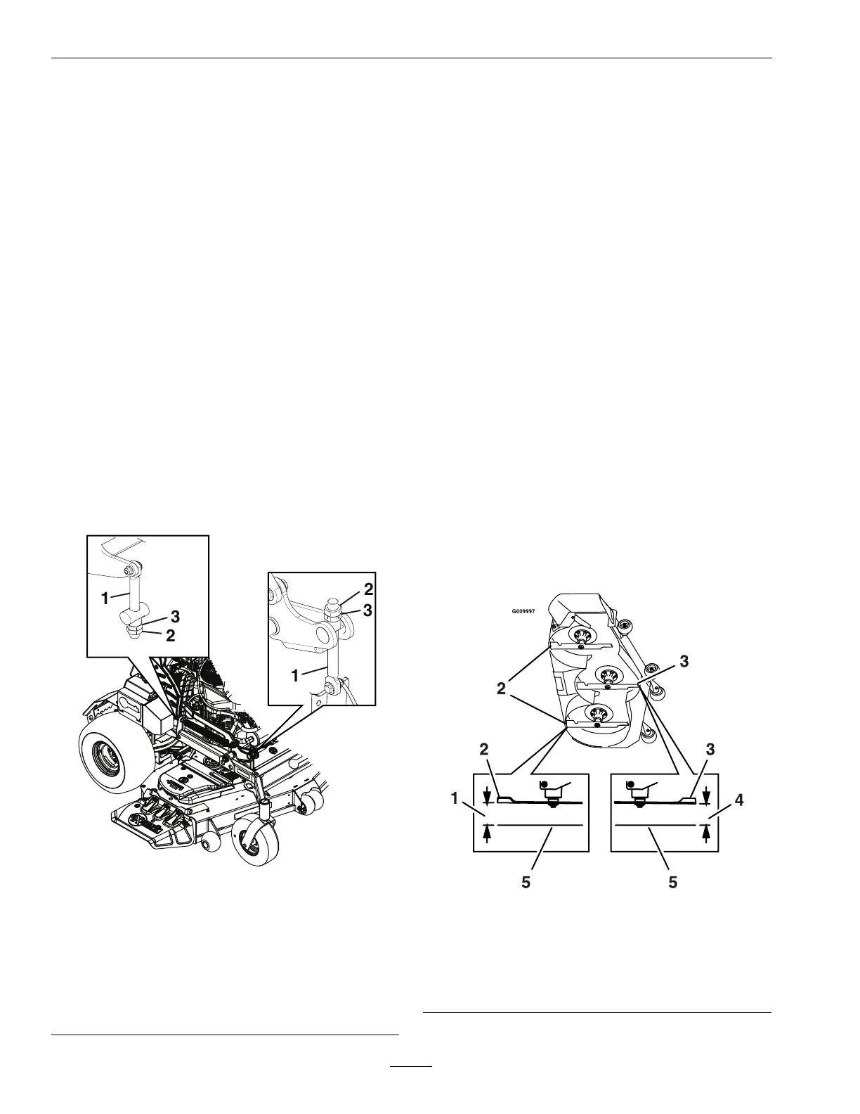
2. Loosen the jam n uts on the top of eac h dec k
adjuster . Fine tune the adjuster on the front dec k
lift assembly b y tur ning it to g et the cor rect height
for the center dec k left and right front blade tips
3. Measure the bac k tip height. Fine tune rear
adjusters as required
4. R e-measure until all four sides are the cor rect
height. Tighten all the jam n uts on the dec k lift
ar m assemblies
g375991
Figure 28
1. Adjuster link 3. Jam nut
2. Adjuster
5. P osition the mo w er on a at surface .
6. Stop engine , w ait for all mo ving par ts to stop , and
remo v e k ey . Eng ag e parking brak e .
7. Chec k the tire pressure in dri v e tires and
pneumatic front caster tires (if equipped). Proper
ination pressure for tires is 13 psi (90 kP a).
Adjust if necessar y
8. Push the button do wn on top of the lev er to
diseng ag e the dec k lift latc h. Pull the handle all
the w a y rearw ard and release the button to latc h
the cutting dec k into the raised transpor t position.
9. Inser t the height adjustment pin into the 3 inc h
(7.6 cm) cutting height location.
10. Slightly pull the handle rearw ard and push the
button do wn on top of the lev er to diseng ag e the
transpor t loc k. Allo w the handle to mo v e forw ard
to lo w er the cutting dec k to the cutting height.
11. Raise the disc harg e deector .
12. Carefully rotate the blades front to rear . Measure
from the lev el surface to the front tip of the
center blade . T he measurement should read 3
inc hes (7.6 cm).
Note: In most conditions , the bac k tips on the
side blades should be adjusted 1/8-1/4 inc h
(3.2-6.4 mm) higher than the front.
g009997
Figure 29
1. 3 1/8-3 1/4 inches
(7.9-8.3 cm)
4. 3 inches (7.6 cm)
2. Back blade tip
5. Level surface
3. Front blade tip
13. Raise the dec k to transpor t position.
50
 Loading...