Maintenance
Hydraulic System Air Purge
Service Interval : As required
Air m ust be purg ed from the h y draulic system
when any h y draulic components , including oil
lter , are remo v ed or any of the h y draulic lines are
disconnected.
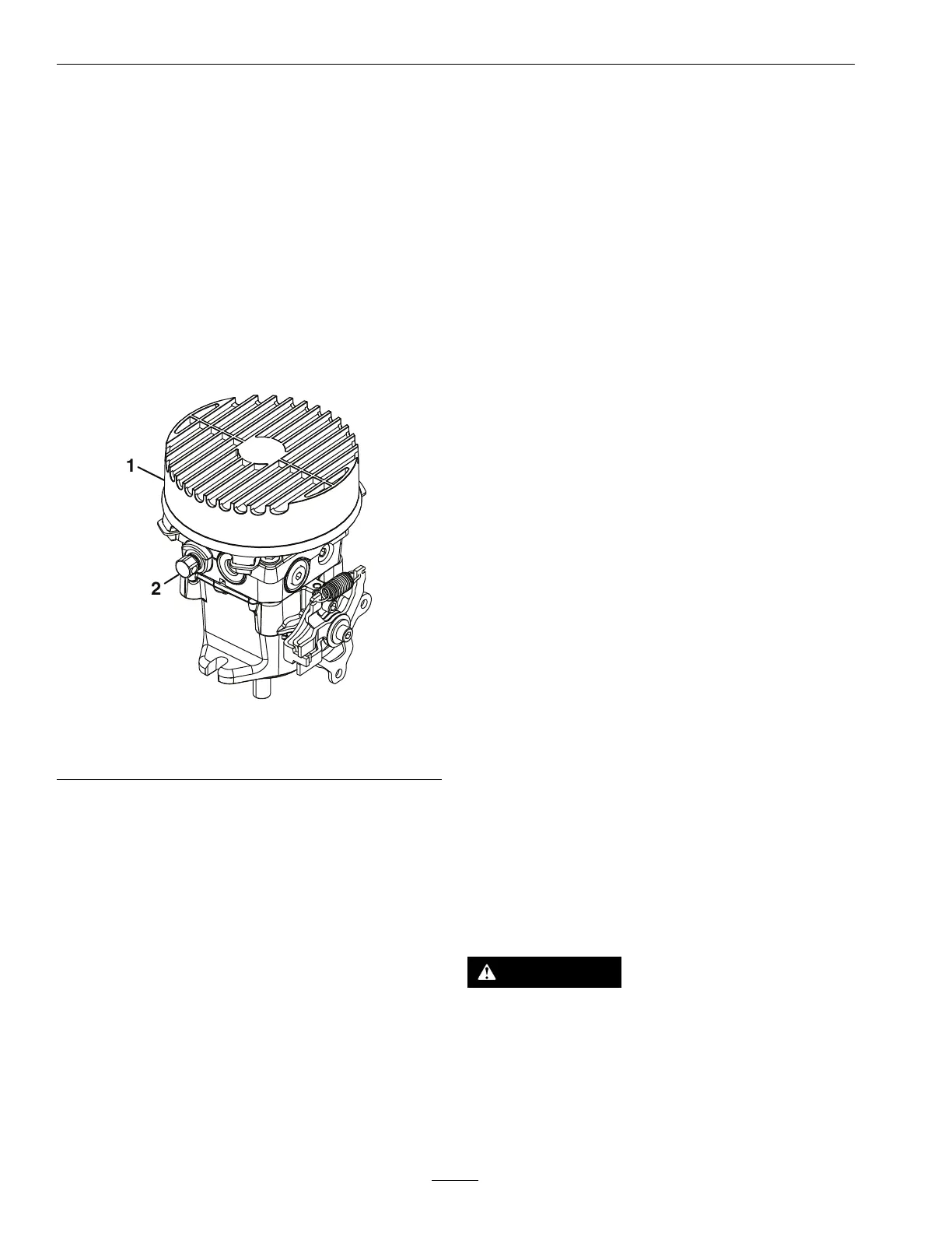
T he critical area for purging air from the h y draulic
system is betw een the oil reser v oir and eac h
c harg e pump located on the top of eac h v ariable
displacement pump ( Figure 27 ). Air in other par ts of
the h y draulic system will be purg ed through nor mal
operation once the c harg e pump is “primed”.
g377574
Figure 27
1. Pump fan and guard
2. Bypass valve
1. Stop engine and w ait for all mo ving par ts to stop .
Raise the rear of the mac hine up onto jac k stands
high enough to raise the dri v e wheels off the
g round.
2. Chec k oil lev el as stated in Check Hy draulic Oil
Lev el section.
3. Star t engine and mo v e throttle control ahead to
full throttle position. Diseng ag e parking brak e
and mo v e motion control lev ers forw ard with
equal pressure .
If either dri v e wheel does not rotate , it is possible
to assist the purging of the c harg e pump b y
carefully rotating the tire in the forw ard position.
Note: It is necessar y to lightly touc h the pump to
c hec k the pump temperature . If the pump is too
hot to touc h, tur n off engine . T he pumps ma y be
damag ed if the pump becomes too hot.
If either dri v e wheel still does not rotate contin ue
with ste p 4 .
4. Open the b ypass v alv e (sho wn in Figure 27 ).
5. With the b ypass v alv e open and the engine
r unning, slo wly mo v e the motion control lev ers
in both forw ard and rev erse directions v e to six
times . As air is purg ed from the unit, the oil lev el
in the reser v oir will drop .
6. Close the b ypass v alv e . With the b ypass v alv e
closed and the engine r unning, slo wly mo v e the
motion control lev ers in both forw ard and rev erse
directions v e to six times .
7. Allo w unit to r un sev eral min utes after the c harg e
pumps are “primed” with dri v e system in the full
speed position. Chec k oil lev el as stated in Check
the Hy draulic Oil Lev el section.
8. Chec k h y dro dri v e linkag e adjustment as stated in
Hy dr o Dri v e Linka ge Adjustment section in
Adjustments .
Wheel Hub Nut
Specication–S-Series
Only
Service Interval : After the rst 100 hours
Every 500 hours thereafter
T or que the n ut on the wheel motor tapered shaft to
211-260 ft-lb (286-352 N-m).
Note: Do Not use anti-seize compound on the
wheel hub .
Check Spark Arrester
(if equipped)
Service Interval : Every 50 hours
W ARNING
Hot exhaust system components may ignite
gasoline v apor s ev en after the engine is stopped.
Hot par ticles exhausted during engine operation
may ignite amma ble materials. Fir e may r esult
in per sonal injur y or pr oper ty dama ge.
Do Not r efuel or r un engine unless spar k ar r ester
is installed.
48
 Loading...