Maintenance
11. Inser t the second bearing and new seal into the
wheel.
12. Apply a thread loc king adhesi v e to the 2nd spacer
n ut and thread onto the axle with the wrenc h ats
facing outw ard.
13. T or que the n ut to 75-80 in-lb (8-9 N-m), loosen,
then re-tor que to 20-25 in-lb (2-3 N-m). Mak e
sure axle does not extend bey ond either n ut.
14. R einstall the seal guards o v er the wheel hub and
inser t wheel into caster fork. R einstall caster bolt
and tighten n ut fully .
Important: T o pr ev ent seal and bearing dama ge,
check the bearing adjustment often. Spin the
caster tir e. T he tir e should not spin fr eel y
(mor e than 1 or 2 r ev olutions) or ha v e an y side
play . If the wheel spins fr eel y , adjust torque on
spacer n ut until ther e is a slight amount of dra g .
R eappl y thr ead locking adhesi v e.
Check Spark Plugs
Service Interval : Every 200 hours
R emo v e spark plugs , c hec k condition and reset g aps ,
or re place with new plugs . See Engine Owner's
Man ual.
Change Fuel Filter
Service Interval : As required
A fuel lter is installed betw een the fuel tank and the
engine . R e place when necessar y .
Note: It is impor tant to reinstall the fuel line hoses
and secure with plastic ties the same as they w ere
originally installed at the factor y to k ee p the fuel line
a w a y from components that could cause fuel line
damag e .
Change Hydraulic System
Filter and Fluid (X-Series)
Service Interval : After the rst 250 hours
Every 500 hours/Y early
(whichever comes
rst) thereafter .
(Every 250 hours/Y early
if using Mobil 1 15W50
thereafter)
Note: Use only Exmark P ar t No . 109-4180 for
Summer use abo v e 32°F (0°C) or P/N 1-523541 for
Winter use belo w 32°F (0°C) (R efer to T ransmission
section in Specications for lter specications).
1. Stop engine , w ait for all mo ving par ts to stop , and
remo v e k ey or spark plug wire(s). Eng ag e parking
brak e .
2. R emo v e and retain the thigh pad and rear guard.
3. Raise the rear of mac hine up and suppor t with
jac k stands (or equi v alent suppor t) just high
enough to allo w dri v e wheels to tur n freely .
CAUTION
R aising the mo w er f or ser vice or maintenance
r el ying solel y on mechanical or h y draulic
jacks could be danger ous. T he mechanical or
h y draulic jacks may not be enough suppor t
or may malfunction allo wing the unit to f all,
which could cause injur y .
Do Not r el y solel y on mechanical or h y draulic
jacks f or suppor t. Use adequate jack stands
or equi v alent suppor t.
4. R emo v e and retain right and left dri v e tires and
lug n uts .
5. Use a catc h pan when draining the h y dro oil.
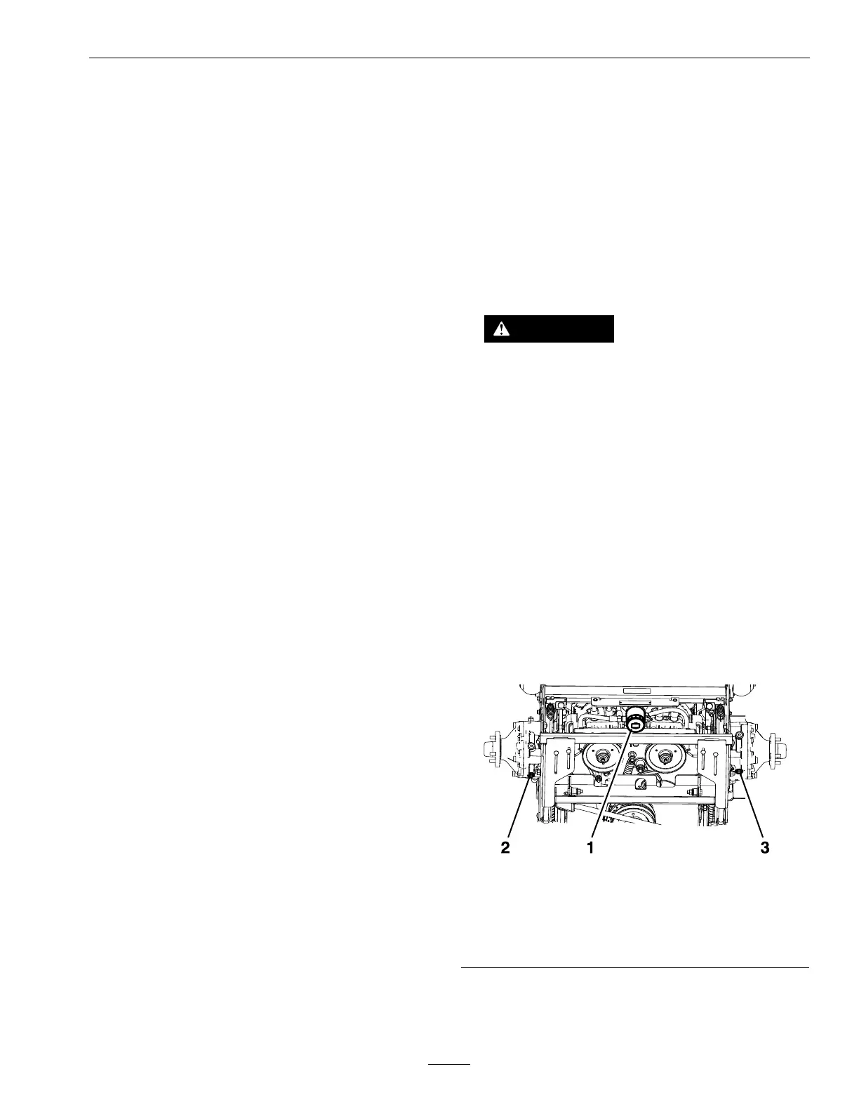
6. T here are three drains that need to be remo v ed to
do a complete uid c hang e . Place a pan under
eac h drain from the follo wing components:
h y draulic lter and the left and right wheel motors .
g451535
Figure 25
Some components removed for clarity
1. Hydraulic lter
3. Right wheel motor plug
2. Left wheel motor plug
7. Carefully clean area around lter . It is impor tant
that no dir t or contamination enter h y draulic
system.
45
 Loading...