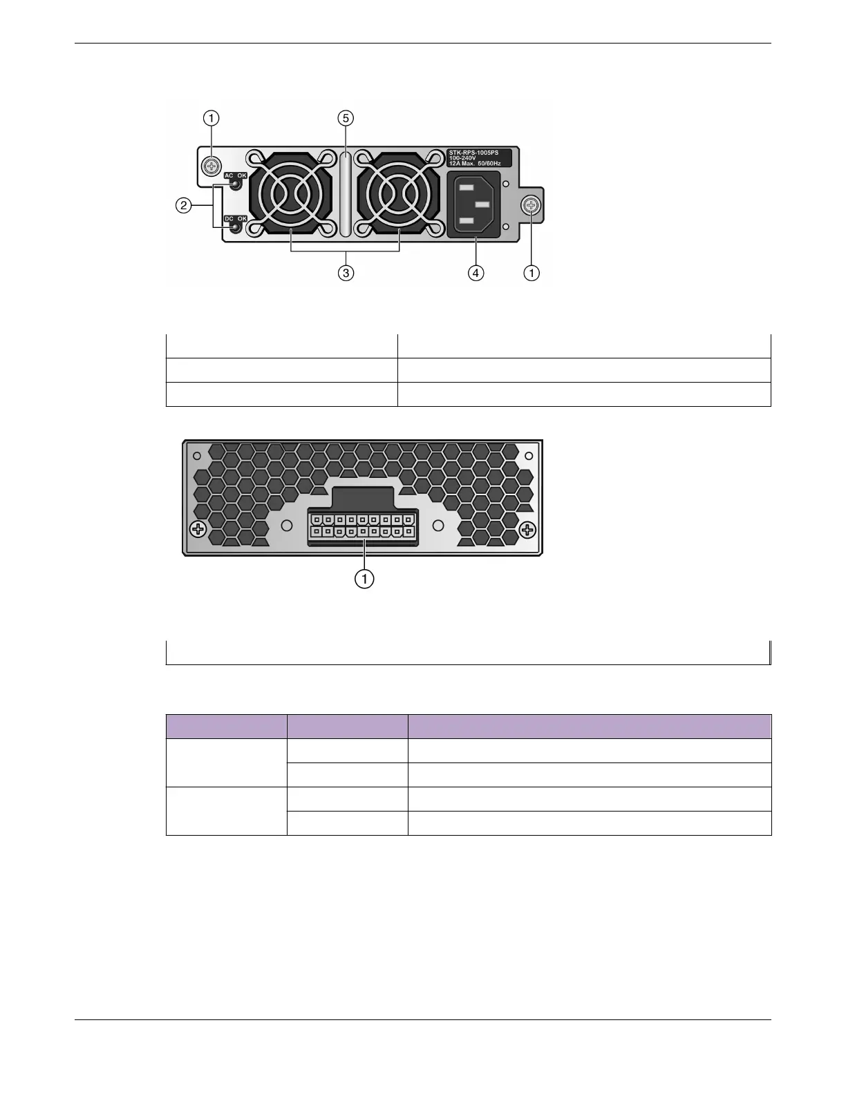
Figure 118: STK-RPS-1005PS Front Panel
1 = Captive screws 4 = AC power input connector
2 = Status LEDs 5 = Handle
3 = Fans
Figure 119: STK-RPS-1005PS Rear Panel
1 = 18-pin Redundant Power Supply connector
Table 45: STK-RPS-1005PS LED Status Definitions
LED LED Color Status
AC OK Green AC input within operational range
O No AC voltage or AC voltage is outside the operational range
DC OK Green Power supply successfully providing 55 VDC to the system
O Power supply malfunctioning
For technical specifications, including pin locations and functions, see STK-RPS-1005PS Redundant
Power Supply Technical Specifications on page 471.
Power Supplies for Use with Your Switch
STK-RPS-1005PS Redundant Power Supply
ExtremeSwitching Hardware Installation Guide 129
 Loading...

