Fan and Acoustic Noise
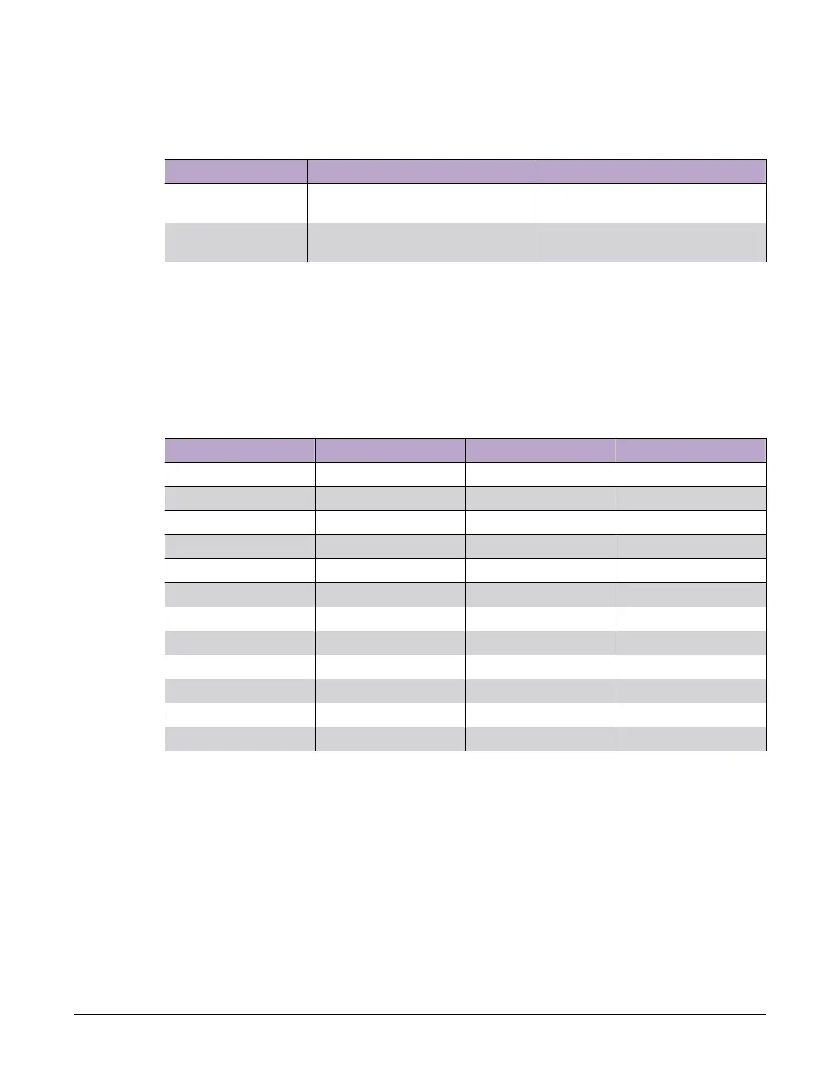
Table 240: Fan and Acoustic Noise
Switch Model Bystander Sound Pressure (at 25°C) Declared Sound Power (at 25°C)
X695-48Y-8C-F
(FB airflow)
52.2 db(A) 6.8 bels
X695-48Y-8C-R
(BF airflow)
50.5 db(A) 6.7 bels
Fan Tray and Speed Variation
Fan speeds are adjusted based on calculations of the temperatures on all sensors. Due to one fan being
located behind the other, air pushed from one fan may cause the other fan in the module to run at a
higher speed. One fan can run at medium speed while the other can spin at high speed if one is close to
the temperature boundary.
Table 241: Fan Tray Speed Variation
Description Operation Status Operation Speed Airflow Direction
Tray 1 Fan 1 up high speed unknown*
Tray 1 Fan 2 up medium speed unknown*
Tray 2 Fan 1 up high speed unknown*
Tray 2 Fan 2 up medium speed unknown*
Tray 3 Fan 1 up high speed unknown*
Tray 3 Fan 2 up medium speed unknown*
Tray 4 Fan 1 up high speed unknown*
Tray 4 Fan 2 up medium speed unknown*
Tray 5 Fan 1 up high speed unknown*
Tray 5 Fan 2 up medium speed unknown*
Tray 6 Fan 1 up high speed unknown*
Tray 6 Fan 2 up medium speed unknown*
*The color of the tab on the fan tray indicates the airflow direction:
• Red = Front-to-Back
• Blue = Back-to-Front
Technical
Specifications Fan and Acoustic Noise
ExtremeSwitching Hardware Installation Guide 435
 Loading...

