MGT FAN P1 P2 S1
CLK ACT LINK
S2
21
22
23
24
17
18
19
20 25
26
27
28 29 30
31
32
36
37
38
39 40
41
42
43
46
44 47
45
48
33
34
35
50
51
49
52
1 2 3 4 5 6 7 8 9
10 11 12 13 14 15 16
CONSOLE
STACK NO.
Management
5
3
4
1
2
Summit
™
X450-G2-48t-10GE4
10GbES FP+
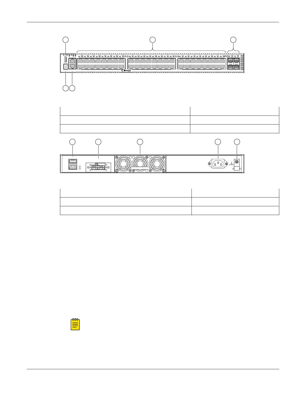
Figure 44: X450-G2-48t-10GE4 Front Panel
1 = Stack number indicator 4 = 10/100/1000BASE-T ports
2 = Console port/Ethernet management port 5 = SFP+ 10GBASE-X ports
3 = USB port
Redundant P ower Input
! See M anual
1
2
SummitStack-V84
4 531 2
Figure 45: X450-G2-48t-10GE4 Rear Panel
1 = 21 Gb stacking ports (QSFP+)
4 = AC power input connector
2 = Redundant power supply (RPS) connector 5 = Grounding screw
3 = Front-to-back fan module slot
ExtremeSwitching X450-G2-24p-GE4 Switch Ports and Slots
X450-G2-24p-GE4 switch ports and slots include:
• 24 front panel PoE+ ports of 10/100/1000BASE-T (ports 1–24).
• Four front panel ports of 1GBASE-X SFP (ports 25–28).
• One front panel USB port.
• Ethernet management port 1 x 10/100/1000BASE-T.
• Serial console port implemented as an RJ45 connector used to connect a terminal and perform local
management.
• One rear slot for fan module with front-to-back
airflow.
• Two dedicated QSFP-form factor 21 Gb stacking ports on the rear panel.
• Rear dual power supply slots with front-to-back airflow.
Note
Unused power supply slots must be covered with blank panels.
ExtremeSwitching X450-G2-24p-GE4 Switch Ports and
Slots ExtremeSwitching Switches
52 ExtremeSwitching Hardware Installation Guide
 Loading...

