RS-232 and IR connectors
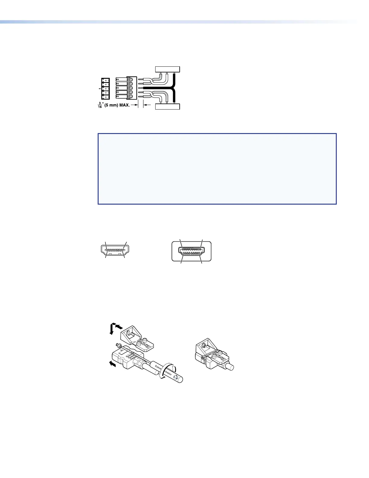
Figure 20 shows how to wire the RS-232 and IR connector.
Tx/Rx
Pins
Rx GTx
RxTx
TxRx
RxTx
Gnd
Gnd
Figure 20. RS-232 and IR Connector Wiring
NOTES:
• The length of exposed wires is critical. The ideal length is 3/16 inch (5 mm).
• If the stripped section of wire is longer than 3/16 inch, the exposed wires may
touch, causing a short circuit.
• If the stripped section of wire is shorter than 3/16 inch, wires can be easily
pulled out even if tightly fastened by the captive screws.
• Do not tin the power supply leads before installing them in the connector. Tinned
wires are not as secure in the connector and could be pulled out.
HDMI connectors
Figure 21 defines the pinout for the HDMI protocol.
HDMI
HDMI
ype A Receptacle
1
18 2
19
182
Figure 21. HDMI Connector
Use the LockIt Lacing Brackets, supplied with the input or output board, to securely fasten
HDMI cables to devices as follows:
1. Plug the HDMI cable into the panel connection (see figure 22,
1
).
3
22
55
44
Figure 22. Installing the LockIt Lacing Bracket
2. Loosen the HDMI connection mounting screw from the panel enough to allow the
LockIt lacing bracket to be placed over it (
2
). The screw does not have to be removed.
XTP II CrossPoint 1600, 3200, and 6400 Switchers • Installation 23