FARO Gage
May 2011
9
Chapter 2: Setup
Hardware Setup
The following sections describe the proper setup of the Gage. This includes
attaching the Gage to your work surface, and connecting the Gage to the
computer.
Mounting the Base
The counterbalance by the tension spring generates torque at the base of the
Gage. So to achieve optimum machine accuracy, the mounting must meet certain
requirements.
N
OTE: The Gage must be mounted in a upright position. Do Not mount the
Gage in an inverted (upside down), or sideways position.
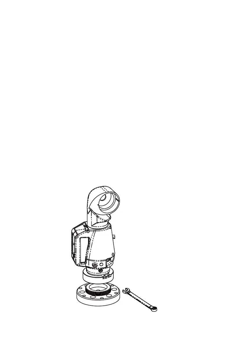
To fasten the Gage:
1 Attach the 3.5" threaded ring and surface mount plate to any stable location.
Tighten all mounting bolts to 100-inch pounds.
2 Place the Gage on top of the 3.5” threaded ring.
3 Screw the threaded collar clamp onto the base of the Gage and the 3.5”
threaded ring.
4 Use the wrench to tighten the threaded collar clamp.
Figure 2-3 Mounting the Gage
08M47E00_FAROGage.book Page 9 Wednesday, June 8, 2011 4:12 PM